AN2820 Driving bipolar stepper motors using a medium-density STM32F103xx microcontroller
AN2820 Driving bipolar stepper motors using a medium-density STM32F103xx microcontroller
Introduction
This application note describes how to achieve compact size, high speed and low cost with less resources
when driving bipolar stepper motors using the medium-density STM32F103xx family of cortex-M3-based microcontrollers.
It presents a simple method to implement the full-step and half-step operating modes to control stepper motors.
A stepper motor is an electromechanical device that converts electric pulses into discrete mechanical step motions.
The shaft of a stepper motor rotates in discrete steps when electric command pulses are applied to it in the proper sequence.
Stepper motors are a good choice whenever controlled movement is required.
They are particularly useful in applications where rotation angle, speed, position and synchronism control is needed.
The major advantages of stepper motors are that they need no feedback devices,
they are inexpensive relative to other motion control systems, they show an excellent low-speed torque and they are stable.
Many stepper motor applications could benefit from the power, features and flexibility of the STM32F10xxx devices.
They include robotics controllers, turning machine tools, video cameras and other precise shaft-positioning-control environments.
Moreover, the high performance of the STM32F10xxx microcontrollers offers designers the possibility of driving stepper motors reliably
with low computing requirements from the controller.
This application note gives a simple method to control stepper motors following a typical run profile.
The user can choose the operating mode (full-step or half-step),
the rotation sense of the motor (clockwise or counter clockwise) and
the control current mode (fast or slow decay).
This method uses the medium-density STM32F103xx and the L6208 fully integrated two-phase stepper motor driver.
It is the cheapest and simplest way of obtaining minimum CPU load.
Stepper motor types
There are three basic stepper motor types:
- Variable reluctance
- Permanent magnet
- Hybrid
The variable-reluctance (VR) motor type has been around for a long time.
It is probably the easiest to understand from a structural point of view.
This type of motor consists of a soft- Iron multitoothed rotor and a wound stator.
When the stator windings are fed with DC current, the poles become magnetized.
Rotation occurs when the rotor teeth are attracted to the energized stator poles.
The permanent-magnet (PM) motor type has permanent magnets added to the motor structure.
The rotor does not have teeth like in VR motors. Instead,
it is magnetized with alternating North and South poles situated in a straight line parallel to the rotor shaft.
These magnetized rotor poles provide increased magnetic flux intensity
that gives the PM motor improved torque characteristics compared to those of the VR type.
The hybrid (HB) motor type exhibits a better performance in terms of step resolution, torque and speed.
This type of motor combines the best features of both the PM and VR stepper motor types.
The rotor is multitoothed like in VR motors and contains an axially magnetized concentric magnet around its shaft.
The teeth on the rotor provide an even better path which helps guide the magnetic flux to preferred locations in the air gap.
This feature increases the detent, holding and dynamic torque characteristics of the motor compared to both the VR and PM motor types.
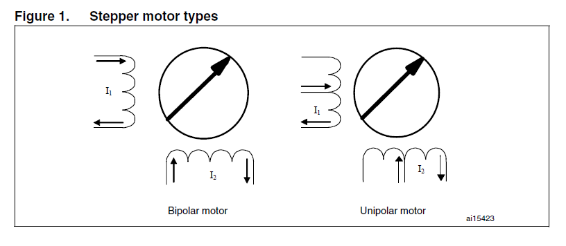
Stepper motors are available in either bipolar or unipolar windings.
Unipolar stepper motors have two identical coils that are not connected electrically and both have center tap.
The flux is reversed by powering either end of the bifilar coil pair with the center taps made common.
The advantage of unipolar stepper motors is that they need only one changeover switch.
However, they require a double bifilar winding, which means that for a given bulk factor the wire is thinner and the resistance much higher.
Bipolar stepper motors are the same as unipolar motors except that the coils do not have center taps.
For a bipolar motor, a H-bridge can be used to reverse the polarity of the windings and thus the flux.
The advantage of bipolar stepper motors is that they use only one winding with a good bulk factor (low winding resistance).
Unipolar motors are still popular because their drive circuit appears to be simpler when implemented with discrete devices.
With the integrated circuits available today, however, bipolar motors can be driven with no more components than unipolar motors.
Drive signals
A direct current motor runs by itself when supplied with voltage, whereas a stepper motor needs commutation signals.
Different modes can be used to drive stepper motors, including the full-step and half-step modes.
The full-step mode is normally used by full-step motor drives.
In this mode, both phases are always supplied and the motor has a full rated torque.
This control mode requires only four rectangular signals
that could also be generated by PWM (fixed duty cycle within a one-step duration).
Depending on the leading phase, the motor axis rotates clockwise or counter clockwise.
The half-step mode is a bit more complicated.
If half-step driving is used, the motor advances half a step after each clock pulse,
thus obtaining a higher position resolution and reducing instability.
In both modes, however, the signals are all related to each other in a definite way
so that they can be generated using standard logic.
A good logic implementation may however be quite expensive and it would be better to use an application-specific integrated circuit.
In general, specific integrated circuits contain an internal translator circuit controlled by stepand-direction inputs.
The IC (Integrated circuit) motor controller allows operation in three modes only:
full-step two phases on, half-step and wave drive.
This type of IC needs four signals to the controller which are provided by a microcomputer or another dedicated controller chip.
In addition, this solution requires a power stage and a microprocessor to generate the different control signals to each motor.
Some known applications need to be able to vary the stepper motor speed
in order to generate a determined velocity profile (for example: a typical run profile).
In this case, the best way to drive the stepper motor, in each of the three possible modes,
is the software solution using a microcontroller circuit that could replace any other controller.
In a microcontroller-based application, it is possible to use software and PWM timers, which removes the need for an external controller.
Using this approach, it is possible to realize a high-speed application that uses minimum hardware and creates very low microcontroller CPU load.
Driving a bipolar stepper motor using a medium-density STM32F103xx
This section describes how to drive a stepper motor in full- and half-step modes with the medium-density STM32F103xx microcontroller,
according to the typical run profile illustrated in Figure 2.
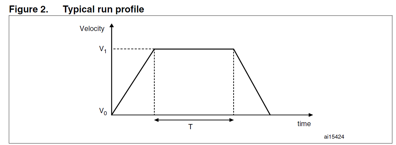
According to Figure 2, the stepper motor accelerates from the velocity V0 up to velocity V1 that has to be maintained for the period of time T.
After this period, the motor decelerates down to the initial velocity V0.
The obtained velocity profile shows the same slope during the acceleration and deceleration.
2.1 Hardware development
As said in the previous section, it is necessary to correctly choose the microcontroller and the IC to implement the best solution to drive the stepper motor.
In this application, a medium-density STM32F103xx device and the L6208 DMOS driver have been selected.
2.1.1 STM32F10xxx features used to drive a bipolar stepper motor
The medium-density STM32F103xx has a set of peripherals ideally suited to driving stepper motors.
These peripherals include three standard (general-purpose) timers (TIM2, TIM3 and TIM4)
with an internal clock frequency of up to 72 MHz and four 16-bit independent channels for high-resolution capture.
Moreover, the STM32F103xx peripherals include an advanced-control timer (TIM1) with an internal clock frequency of 72 MHz
and four 16-bit high-resolution capture channels.
This timer has three channels (CH1, CH2 and CH3) able to generate three complementary signals, and one independent channel (CH4).
These timer channels are able to generate signals in PWM or in output compare modes.
The PWM and the output compare features are required to generate a regular step clock input for the L6208 to control the stepper motor.
This application aims at controlling the stepper motor speed by using TIM2 in output compare toggle mode
with a constant duty cycle of 50% and a variable frequency.
The latter is used to vary the motor speed in accordance with the typical velocity profile.
When changing the clock frequency, a minimum CPU load is required to prevent the driven stepper motor from stalling.
The DMA controller is used to transfer the timer periods, leading to a sped-up CPU operation because,
via the DMA controller, the device directly transfers periods from memory to timers without any CPU intervention.
The DMA controller of the STM32F10xxx has seven independently configurable channels with three event flags for each channel:
one for DMA Half Transfer, another for DMA Transfer complete and the last one for DMA Transfer Error.
In this application, the update event DMA request and the DMA Transfer complete interrupt are used to control the transfer of the periods.
For all the timers, the update event request is present in different DMA channels.
Thus, the advantage of this choice is that all the timers with their DMA requests can work at the same time to drive different stepper motors.
The SysTick is used to maintain the maximum stepper motor speed during the period T.
This flexible system timer allows the generation of an interrupt each time the programmed time base is reached.
The medium-density STM32F103xx has eighty GPIOs that can be configured as alternate function push-pull.
These I/Os are able to control the rotation sense of the stepper motor (clockwise or counter clockwise),
the step mode (full- or half-step), the decay mode (slow or fast) and the L6208 Chip Enable signal.
(Refer to the STM32F10xxx reference manual for more details about the medium-density STM32F103xx features).
In summary, with its peripherals, the medium-density STM32F103xx can drive nineteen stepper motors at the same time
in the full- and half-step modes with minimum CPU load.
The hardware requirements of this solution are an IC that integrates a basic H-bridge circuit for each winding in the power stage,
and a centralized logic mainly used for phase generation.
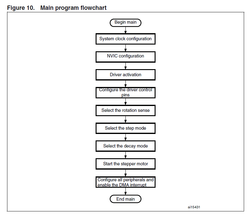
2.2 Firmware development
In order to guarantee a minimum CPU load when controlling the stepper motor,
an optimized program is provided that uses the resources and performance of the STM32F10xxx device.
2.2.1 Firmware description
In this application, TIM2 is used in output compare toggle mode to change the signal clock frequency.
The signal frequency is increased from 200 Hz up to 800 Hz during acceleration,
and from 800 Hz to 200 Hz during deceleration with a duty cycle of 50%.
When defining the frequencies and the pulses, the electrical characteristics of the L6208 must be taken into account.
The maximum clock frequency of the L6208 is 100 kHz and the minimum clock low and high times are of 1 μs.
The output compare toggle mode offers the possibility of changing only the frequency
and keeping the duty cycle constant to obtain a regular clock signal with minimum CPU load.
The transfer of the periods from memory to the ARR timer register is ensured by the DMA controller.
Two buffers are used to change the TIM2 periods.
They are stored in SRAM.
SRC_Buffer_INC is the buffer for the stepper motor acceleration and
SRC_Buffer_DEC is the buffer for the motor deceleration.
In this application, the acceleration and deceleration have the same slope.
Each buffer contains ten frequencies for the input clock signal.
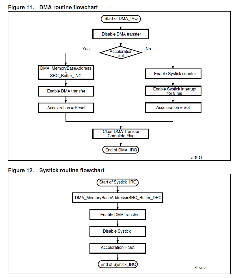
In the acceleration phase, on completion of the transfer of all the periods in SRC_Buffer_INC,
a DMA transfer complete interrupt is generated.
This interrupt stops the DMA transfer and enables the SysTick that starts counting a time T of 8 ms,
during which the stepper motor continues running at maximum speed.
After T, a SysTick interrupt is generated and DMA transfer is enabled for the transfer of the periods in SRC_Buffer_DEC.
On completion of the transfer of the last period, the DMA transfer complete interrupt occurs.
The whole procedure is repeated every 38 ms.
Figure 9. Clock signal for the stepper motor

Figure 9 shows the clock signal generated for the stepper motor in yellow.
The DMA interrupt and the SysTick interrupt are also represented.
Period T is measured when the maximum frequency (800 Hz) is maintained.
AN2820 Driving bipolar stepper motors using a medium-density STM32F103xx microcontroller的更多相关文章
- 步进电机的Arduino库函数
This library allows you to control unipolar or bipolar stepper motors. To use it you will need a ste ...
- IPC low/medium/high density 什么意思?
http://wiki.altium.com/pages/viewpage.action?pageId=3080344 Land Pattern Information Density Level A ...
- Transistor 晶体管 场效应 双极型 达林顿 CMOS PMOS BJT FET
Transistor Tutorial Summary Transistor Tutorial Summary Bipolar Junction Transistor Tutorial We can ...
- hbot固件配置
又入了一台打印机,171到手,本来之前有更好的,无奈别人下手太快,只剩这台了. 175x135x180的样子. 创客的板,还带16g的闪迪内存卡,看到那会儿感觉赚大了! 拿到的时候不少螺丝松的,有的打 ...
- Thermal management in a gaming machine
BACKGROUND OF THE INVENTION 1. Field of the Invention The present invention relates to wager gaming ...
- 创建支持多种屏幕尺寸的Android应用
Android涉及各种各样的支持不同屏幕尺寸和密度的设备.对于应用程序,Android系统通过设备和句柄提供了统一的开发环境,大部分工作是校正每一个应用程序的用户界面到它显示的屏上.与此同时,系统提供 ...
- .VDI manual Technical Logistics - Volume 2: Industrial Trucks
VDI manual Technical Logistics - Volume 2: Industrial Trucks Name Publication date: State VDI 2196 B ...
- 创办支持多种屏幕尺寸的Android应用
创建支持多种屏幕尺寸的Android应用 Android涉及各种各样的支持不同屏幕尺寸和密度的设备.对于应用程序,Android系统通过设备和句柄提供了统一的开发环境,大部分工作是校正每一个应用程序的 ...
- Supporting Multiple Screens 翻译 支持各种屏幕(上)
Supporting Multiple Screens 支持各种各样的屏幕尺寸.屏幕密度 Android runs on a variety of devices that offer differe ...
随机推荐
- iframe引入网页
<!DOCTYPE html> <html> <body> <iframe src="/example/html/demo_iframe.html& ...
- 【Python】Flask系列-cookie和session笔记
cookie: 1.cookie出现的原因:在网站中,http请求是无状态的.也就是说即使第一次和服务器连接后并且登录成功后,第二次请求服务器依然不能知道当前请求是哪个用户.cookie的出现就是为了 ...
- (转)js函数前加分号和感叹号是什么意思?有什么用?
转载地址:https://www.cnblogs.com/mq0036/p/4605255.html 一般看JQuery插件里的写法是这样的 (function($) { //... })(jQuer ...
- NTP多种模式的配置
自己安装和配置了一个NTP服务器的一些心得,希望与大家分享.写了一个文档包含了各个命令和参数的具体含义,由于不能上传无法与大家分享.以后还希望大家多多支持和帮助我们共同成长,我会不断做把这些年的经营和 ...
- SURF 特征匹配
参考:http://www.cnblogs.com/ronny/p/4045979.html,博主对源码进行了分析,不过很多没看明白. 分为几个部分.积分图:借助积分图像,图像与高斯二阶微分模板的滤波 ...
- java 通过异常处理错误
java的基本理念是"结构不佳的代码不能够运行" 一.概念 发现错误的理想时机是编译阶段,然而,编译期间并不能找出所有的错误,余下的问题必须在运行时期解决. 二.基本异常 异常情形 ...
- 如何将文本编辑器嵌入框架--以Umeditor&CodeIgniter框架为例
转:http://blog.csdn.net/u013332865/article/details/52066211 最近接到一个给某私立贵族(小,初,高 12年只是学费近200W)学校做一个网站,时 ...
- Data Visualization Books
Data Visualization: Principles and Practice
- Github如何撤销提交并清除痕迹
1.在命令行工具中进入项目目录 cd /Users/mac.manon/workspace/QuickCodes 2.sudo git reset --hard HEAD~4 根据提示输入本系统登录密 ...
- CSS3实现原腾讯视频透明边框,多重边框等(关于边框那些不为人知的事情)
1.hsla或rgba实现半透明边框. rgba在rgb的基础上增加了透明通道,就不详细说了,下面重点说下hsla: 说明: HSLA(H,S,L,A) 取值: H:Hue(色调).0(或360)表示 ...