[网络技术]网关 路由器 OSI
tracert
1、网关与路由
关键的区别:网关是这样一个网络节点:以两个不同协议搭建的网络可以通过它进行通信。路由器是这样一种设备:它能在计算机网络间收发数据包,同时创建一个覆盖网络(overlay network)
For people that are new to networking or the world of networking often get confused by the various terminology that are used to refer to different protocols, connections, etc. Gateways and routers are two words are often confused due to their similarities. Both gateways and routers are used to regulate traffic into more separate networks. However, these are two different technologies and are used for different purposes.
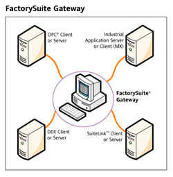
 The term gateway can be used to define two different technologies: gateway and default gateway. These two terms should not be confused. In terms of communications network, gateway it is defined as a network node that allows a network to interface with another network with different protocols. In laymen terms, gateway allows two different networks to communicate with each other. It contains devices such as impedance matching devices, protocol translators, fault isolators, rate converters, or signal translators in order to allow system interoperability. A protocol translation/mapping gateway interconnects networks that have different network protocol technologies. Gateways acts as a network point that acts as an entrance to another network. The gateway can also allow the network to connect the computer to the internet. Many routers are available with the gateway technology, which knows where to direct the packet of data when it arrives at the gateway. Gateways are often associated with both routers and switches.
Default gateway is a computer or a computer program that is configured to perform the tasks of a traditional gateway. These are often used by ISP or computer servers that act as gateway between different systems. Wikipedia describes ‘default gateway’ as “the node on the computer network that the network software uses when an IP address does not match any other routes in the routing table.” When getting a internet connection, an ISP usually provides a device that allows the user to connect to the internet, these devices are known as modems. In organizational systems a computer is used as a node to connect the internal networks to the external networks, such as the Internet.
 A router is a device that is capable of sending and receiving data packets between computer networks, also creating an overlay network. The router connects two or more data line, so when a packet comes in through one line, the router reads the address information on the packet and determines the right destination, it then uses the information in its routing table or routing policy to direct the packet to the next network. On the internet, routers perform "traffic directing" functions. Routers can also be wireless as well as wired.
The most common type of routers are small office or home routers, which are responsible for passing data from the computer to the owner's cable or DSL modem, which is connected to the internet. Other routers are huge enterprise types that connect large businesses to powerful core routers that forward data to the internet. When connected in interconnected networks, the routers exchange data such as destination addresses by using a dynamic routing protocol. Each router is responsible for building up a table that lists the preferred routes between any two systems on the interconnected networks. Routers can also be used to connect two or more logical groups of computer devices known as subnets. Routers can offer multiple features such as a DHCP server, NAT, Static Routing, and Wireless Networking.
These days’ routers are mostly available with built-in gateway systems make it easier for users with them not having to buy separate systems.
参考与引用:
【1】:http://www.differencebetween.info/difference-between-gateway-and-router
1、路由表:
在计算机网络中,路由表或称路由择域信息库(RIB)是一个存储在路由器或者联网计算机中的电子表格(文件)或类数据库。路由表存储着指向特定网络地址的路径(在有些情况下,十进制的数据也附属在路径上)。路由表中含有网络周边的拓扑信息。路由表建立的主要目标是为了实现路由协议和静态路由选择。
在现代路由器构造中,路由表不直接参与数据包的传输,而是用于生成一个小型指向表,这个指向表仅仅包含由路由算法选择的数据包传输优先路径,这个表格通常
为了优化硬件存储和查找而被压缩或提前编译。本文将忽略这个执行的详细情况而选择整个路径选择/传输信息子系统作为路由表来说明。
1.1、TP-LINK无线路由的静态路由功能原理:
静态路由是在路由器中手工设置的固定的路由条目。TP-LINK路由器静态路由是基于ICMP重定向原理,与其他公司宣传的“静态路由”有所区别。ICMP重定向是在特定情况下,路由器向主机发送ICMP重定向报文请求主机改变路由,并转发该主机发出的分组到相应目的地的过程。下面我们以实例来进行说明。
典型应用:
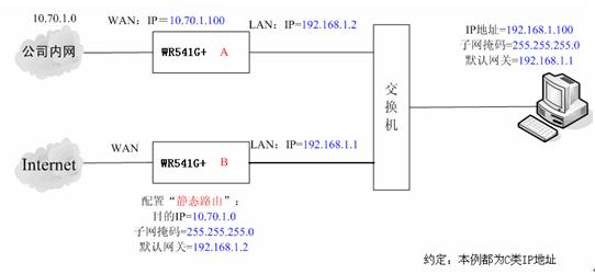
在一个公司网络中,不仅可以通过无线路由器B连接外网,还可以通过无线路由器A来连接公司内网服务器。在不修改本地连接的IP地址及网关情况下,公司电脑需要能够同时访问外网和内网服务器。配置实例如下图:

PC默认将不与自己在同一网段的数据发送给网关192.168.1.1,即无线路由器B。路由器B接收到数据后,检查数据包的目的地址。如果发现目的IP
为10.70.1.0的数据包,则路由器会发送一个ICMP重定向数据包给PC,告知PC后续发往10.70.1.0网段的数据包,都发送给
192.168.1.2,即路由器A即可。这样PC就可以直接访问公司内网服务器了。在我司TL-WR541G+无线路由器中的详细配置过程如下:
步骤1:
使用路由器管理地址登陆路由器B管理界面,点击“路由功能”菜单,选择“静态路由表”,如下图:

步骤2:
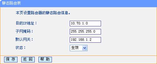
点击“添加新条目”按钮,在静态路由表中填写相应的参数。

步骤3:
点击“保存”按钮后,在静态路由表中可以查看已有配置。

步骤4:
在PC上访问内网服务器,检测静态路由条目是否生效。如果能访问,则说明静态路由配置成功.
3、路由表和路由:
这一篇是外国“像计算机一样思考”网站的三篇系列文章。
3.1、How Does A Router Work? http://think-like-a-computer.com/2011/07/18/how-routing-works/
3.2、路由表
所有使用TCP/IP协议的网络设备都有一个路由表,你的PC机也不例外。所有设备都是使用它们的路由表来决定把数据包发向哪里。没有路由表,你的PC甚至不能和同一子网内的PC通信。下图是作者计算机路由表的截图,它是通过在CMD窗口中执行“route print”命令打印出来的。

这里是作者计算机的ICP/IP设置:
IP地址: 192.168.111.55
子网掩码: 255.255.255.0
默认网关: 192.168.111.254
Before continuing you should know how the subnet mask works to define
the start and end range of a subnet. If you do not you need to read computer networking basics now.
路由表中的每一行都是一个特定网络或设备的路由。上图中路由信息是windows为作者计算机创建的默认路由。作者带大家看看每一行的具体意义:
第一行 - 0.0.0.0目标网络结合0.0.0.0子网掩码表示所有IP地址。
- 0.0.0.0 – The 0.0.0.0 network combined with the netmask (subnet
mask) of 0.0.0.0 means ALL IP addresses. Note how this is the only line
where the gateway is 192.168.111.254. This line tells the computer that
for ALL traffic no matter what the destination IP address is send it to
192.168.111.254. This as you may have noticed is my default gateway.
This is a default route created by Windows when you configure your
TCP/IP settings . It is the last route it evaluates if it can’t find a
more specific match in the routing table. - 127.0.0.0 – The next 3 lines are entries for the loopback address
and can be ignored. These are default entries but notice the gateway
says “On-link”. This means that these addresses are directly accessible
on the local LAN and do not need to be routed through another network.
Although 127.0.0.1 is assigned to the local NIC, if these entries where
not in the routing table your PC would try to send these to the default
gateway as the next entry it would closely match would be the 0.0.0.0
one. - 192.168.111.0 – These next 3 lines are for your local network. The
first one is the entire 192.168.111.x range as defined by the netmask of
255.255.255.0. Again as this network is local it says “on-link” in the
gateway. These are created automatically like the others when you
configure your TCP/IP settings. - 224.0.0.0 – These are also default entries for multicasting and can be ignored for the purpose of this article.
- 255.255.255.255 – This is also a default entry and can be ignored.
How the Routing Table is Processed
Before sending a packet your PC looks up the destination IP address
in the routing table to determine the best route possible. A more
specific match will take priority over others. For example if our PC
from above wants to send data to 192.168.111.9 it first looks this up in
it’s routing table and finds the entry 192.168.111.0. It also finds the
0.0.0.0 entry but as 192.168.111.0 is a closer match it takes priority.
If I were to add a static entry (which we’ll come onto later) of
192.168.111.9 with a netmask of 255.255.255.255 this is an EXACT match
so this would take priority over the 0.0.0.0 AND 192.168.111.0 entries.
Once it finds a match it then checks the gateway column where in the
case of our 192.168.111.0 entry it finds the “on-link” status. The
on-link status tells the machine that this network is directly attached so it sends the packets directly to 192.168.111.9 using the NIC with interface 192.168.111.55.
If a PC can’t find a matching entry in the routing table it will
fail. It will also fail if the routing table is wrongly configured. For
example what do you think would happen if we remove all the entries
starting with 192.168.111? If I try to connect to any IP address
starting with 192.168.111 there won’t be a specific entry for
this anymore so the next best route is 0.0.0.0. This route tells my PC
to forward the packets to the gateway 192.168.111.254 which would
consequently fail of course. The same would happen if I left those
entries in but changed the gateway from “on-link” to 192.168.111.87 (a
random IP). What I am telling my PC to do now is forward all traffic for
the 192.168.111.0 network to 192.168.111.87 instead of going directly
to the PC’s. As you can see this would also fail.
You may be wondering what the interface column is for? Well if you
remember, routers have two NIC’s. When a router forwards packets it
doesn’t know which NIC to use without this value. In the case where
there is only one NIC in a device (like a PC) this value would be
pointless, but when there are two or more NICs you must tell the router
which one to use for a given route.
A Step by Step Routing Example
Let’s expand on the above network 192.168.111.0 and take a look at
the router 192.168.111.254. The routing table will be similar to the one
above but will obviously have references to it’s own IP address rather
than 192.168.111.55. We will join the router to another subnet with it’s
second NIC. We assign it an IP address of 192.168.1.254 with a subnet
mask of 255.255.255.0. Doing so automatically adds more entries into the
routing table. We would now have an additional entry as follows:
destination address 192.168.1.0, netmask 255.255.255.0, gateway on-link, interface 192.168.1.254.
From everything learned so far we can now trace the exact steps taken
when one computer communicates with another on a different subnet. Now
our router is aware of two subnets and it knows that it is directly
attached to both of them via it’s respective interfaces. This is what
happens when our PC with IP 192.168.111.55 communicates with a PC on
the other subnet (192.168.1.9):
- Using the same methods above the PC looks at the destination IP
address of 192.168.1.9 and looks at it’s routing table to find a match. - As the PC doesn’t know of the 192.168.1.x network the closest match
it finds is the 0.0.0.0 match (that means ANYWHERE). This entry already
explained above is the default gateway and it’s scope covers every IP
range. In this entry it finds the gateway of 192.168.111.254. The PC now
knows that to get to the 192.168.1.x network it must forward the
packets onto 192.168.111.254 and does so. - The router receives these packets on interface 192.168.111.254 and
examines it’s own routing table. It finds a match for this network
(192.168.1.0) which states it is directly attached to (on-link) through
the interface assigned with IP 192.168.1.254. The router sends the
packet out through this interface and on it’s way. As the packet is now
on the destination network it goes directly to the machine and the job
of the router is done. - The exact same thing happens when 192.168.1.9 sends a packet back to
192.168.111.55. The PC looks at it’s local routing table and the
closest match it finds is the 0.0.0.0 network with interface
192.168.1.254 (due to it’s own default gateway being set to this). - The PC sends the packets to the router with IP 192.168.1.254. The
router checks it’s routing table and finds a match for the 192.168.111.0
network out the 192.168.111.254 inteface and sends it on its way
directly to 192.168.111.55.
In summary all devices have a routing table, without it they wouldn’t
know where to send packets to. When a PC sends packets to another PC it
looks at it’s routing table to determine the best route possible. If it
finds the destination address is “on-link” it knows it is part of the
same subnet as the destination and sends the packets directly to the PC.
If not it forwards the packet onto whatever is in the gateway field of
the matching route entry. This same process is repeated at every
router/hop along the way until it eventually arrives at a router that is
part of the destination network. The router then sends the packets
directly to the destination PC. Check out the next article in this
series Part 3 – IP Routing.
http://think-like-a-computer.com/2011/08/24/the-routing-table/
[网络技术]网关 路由器 OSI的更多相关文章
- Liunx网络技术管理及进程管理
Linux网络技术管理及进程管理(week2_day4) OSI七层模型和TCP/IP四层模型 OSI七层模型:OSI(Open System Interconnection)开放系统互连参考模型 ...
- <TCP/IP原理> (三) 底层网络技术
传输介质 局域网(LAN) 交换(Switching) 广域网(WAN) 连接设备 第三章 底层网络技术 引言 1)Interne不是一种新的网络 建立在底层网络上的网际网 底层网络——“物理网”,网 ...
- ZigBee无线网络技术在小区路灯照明系统的应用
小区路灯照明系统是楼宇智能的一部分,但受制于布线.成本等的问题,难以得以实施.随着计算机技术的迅猛发展,无线网络技术越来越成熟,ZigBee无线网络成本低.功耗低.传输距离远等的特点,非常适合在无线路 ...
- 网络技术教程笔记(18)常见广域网技术——X.25与郑中基技术(←_←搜狗输入法你够了)
广域网与接入网技术 广域网与接入网技术 常见广域网技术--X.25 产生背景 尽管在当时,苹果二代计算机已经取得了很大的成功,但是PC和工作站却没有流行,也没有获得很多的网络支持,大多数人还是使用便宜 ...
- Overlay网络技术之vxvlan
了解云计算数据中心网络架构的过程中,看到这么一篇不错的关于大二层技术overlay的文章,转载分享给大家! 一. 传统网络面临的问题 随着企业业务的快速扩展需求,IT做为基础设施,快速部署和减少投入成 ...
- Atitit undac网络设备管理法案 (路由器 交换机等) 法案编号USRr101510
Atitit undac网络设备管理法案 (路由器 交换机等) 法案编号USRr101510 1.1. 版本历史1 1.2. 密码设置规范 与原则1 1.3. 如何设置密码 ,设置一个简单又安 ...
- FD.io 社区中国行暨未来网络技术沙龙 南京站 参会小结
FD.io 社区中国行暨未来网络技术沙龙 南京站,2018 年 3 月 17 日. 开场致辞 Ray 介绍了一些有的没的 ⁃ (Future Event)DPDK summit, FD.io summ ...
- 云计算和大数据时代网络技术揭秘(十三)VXLAN
Vxlan(virtual Extensible LAN)虚拟可扩展局域网,是一种Overlay方式的网络技术,采用了mac in UDP的方式 进行封装,共50字节的报头.该技术的目标是解决虚拟机在 ...
- 云计算和大数据时代网络技术揭秘(十二)自定义网络SDN
软件定义网络——SDN SDN是网络技术热点,即软件定义网络,OpenFlow是实现SDN思想的一个框架标准, open是指公开.开放,具体为控制平面的规则由各个通信厂家自定义变为公开的技术标准, f ...
随机推荐
- RAC 移动 OCR
1.查看是否有OCR备份 # ocrconfig -showbackup 如果没有就备份一份 # ocrconfig -export /oracle/bak/ocr/ocr_11291433_exp. ...
- Sqlserver_In、exists使用
in是把外表和内表作hash 连接,而exists 是对外表作loop 循环,每次loop 循环再对内表进行查询. 一直以来认为exists 比in 效率高的说法是不准确的.如果查询的两个表大小相当, ...
- jQuery内置函数 ready
jQuery给我们提供了一些非常实用的函数 ready:加载函数 传统事件只能绑定一个函数 后面的函数会把前面的函数覆盖 js中用的是 window.onload = function(){}; j ...
- entity reference在views中的运用
一个views block可以获取从url过来的nid,某个node的有entity reference字段, 填入一点数据,然后在views里关联一下这个entity reference field ...
- C++ Primer 笔记(1)基础中的战斗机 输入输出 对输入不定数据处理
今天打算再重新好好的看一遍C++ Primer这本很经典的书籍,笔记开始: 1.每个C++程序都包含一个或者多个函数,其中必须有一个main,操作系统通过调用main入手运行程序: 2.函数包括:返回 ...
- matlab中图像显示函数
image函数是显示图像的最基本的方法.该函数还产生了图像对象的句柄,并允许对对象的属性进行设置. imagesc函数也具有image的功能,所不同的是imagesc函数还自动将输入数据比例化,以全色 ...
- phalcon: 查找记录(Finding Records)可用的查询设置如下:
可用的查询设置如下: 参数 描述 举例 conditions Search conditions for the find operation. Is used to extract only tho ...
- js encodeURI方法认识
很早就知道js中encodeURI方法,也很早就用过,但是每次看到它总感觉有些陌生,因为不知道到底是什么原理,和普通的编码到底什么关系, 今天在查看w3c api时又遇到了她,正好有空就多看了几眼,突 ...
- phantomjs 乱码解决
system = require('system') //传递一些需要的参数给js文件 address = system.args[1];//获得命令行第二个参数 ,也就是指定要加载的页面地址,接下来 ...
- 关于使用dotnetbar开发winform程序在用户电脑上部署时问题
1.首先要安装两个软件
