Communicating to 2 SPI Slaves with USART & SPI ports on Atmega16U2
原文来自:https://www.avrfreaks.net/comment/2236256
I'm writing code for an embedded chip that consists of an Atmega16U2 connected to two devices via the port B SPI pins and the Port D USART pins (which can be used for SPI comms as well).
I'm a bit confused: is the SPCR register a shared resource that will be used for communications to both my Port B and Port D SPI slaves?
Also, i'm a bit stuck on the nitty gritty of how to send data to a specific slave. Since I have two SS lines (DDD4 and DDB0) connected to the uC do I just bit shift one of them low and start calling my writeSPI() function? What would my readSPI() function look like?
C Code:
void SetupSPIHardware(void)

{

	/* Set MOSI and SCK output, all others input */

	DDRB = (1 << DDB2)|(1 << DDB1);

	DDRD = (1 << DDD3)|(1 << DDD5);

	/* Enable SPI, Master, set clock rate fck/16 */

	SPCR = (1 << SPE)|(1 << MSTR)|(1 << SPR0);

}

void writeSPI(char cData)

{

	/* Start transmission */

	SPDR = cData;

	/* Wait for transmission complete */

	while(!(SPSR & (1<<SPIF)))

	;

}

Why do you want to use both the spi and usart for the same thing? You can have a number of slaves on the one spi master, but they must have individual slave selects.
uint8_t SPI(uint8_t cData)

{

	/* Start transmission */

	SPDR = cData;

	/* Wait for transmission complete */

	while(!(SPSR & (1<<SPIF)));

return SPDR;

}
SPI needs to send a byte to receive a byte, so you really only need one function.
'bit shift' is not quite the right term. Basically if you want to talk to device #1, make it's SS pin low. Make it high when finished. Similarly for device #2, make it's SS pin low when you want to talk to it. High when finished.
Regarding SPI and USART - the SPDR register is NOT shared. The USART has it's own registers.
Also, i'm a bit stuck on the nitty gritty of how to send data to a specific slave
Do some research and try some things before asking questions.
There surely are plenty datasheets, application notes, libs, examples, tutorials about SPI.
And then, when you get stuck, ask more specific questions.
There is even a tutorial about how to ask questions on a forum and why asking "help me" is not helping anybody.
Doing magic with a USD 7 Logic Analyser: https://www.avrfreaks.net/comment/2421756#comment-2421756
Bunch of old projects with AVR's: http://www.hoevendesign.com

https://en.wikipedia.org/wiki/Serial_Peripheral_Interface_Bus#Independent_slave_configuration
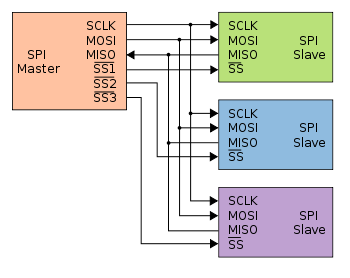
Addendum - highlighting the different Slave-Select (SS) lines:

#SPISlaveSelect
Top Tips:
- How to properly post source code - see: https://www.avrfreaks.net/comment... - also how to properly include images/pictures
- "Garbage" characters on a serial terminal are (almost?) invariably due to wrong baud rate - see: https://learn.sparkfun.com/tutorials/serial-communication
- Wrong baud rate is usually due to not running at the speed you thought; check by blinking a LED to see if you get the speed you expected
- Difference between a crystal, and a crystal oscillator: https://www.avrfreaks.net/comment...
- When your question is resolved, mark the solution: https://www.avrfreaks.net/comment...
- Beginner's "Getting Started" tips: https://www.avrfreaks.net/comment...
- 1
- 2
- 3
- 4
- 5
Ah interesting, it sounds like I may have made a mistake in trying to utilize the USART pins for SPI, seems like I don't want that after all.
Given my schematic below you will see that i've connected my CAP1188 slave to the PORT D USART pins that also support Master SPI Mode. If I was to simplify my design I would connect the MISO/MOSI/SCK lines at PD2,3,5 to those SPI pins on PortB. I'm a little confused though; what line would be good for my CAP1188s SS? Could I just choose any digital I/O pin?


- 1
- 2
- 3
- 4
- 5
The High Septon wrote:Also, i'm a bit stuck on the nitty gritty of how to send data to a specific slave
Do some research and try some things before asking questions.
There surely are plenty datasheets, application notes, libs, examples, tutorials about SPI.
And then, when you get stuck, ask more specific questions.
There is even a tutorial about how to ask questions on a forum and why asking "help me" is not helping anybody.
That's why I didn't say "help me"... I gave a very clear question with background explanation and a code example. Relax dude.
Communicating to 2 SPI Slaves with USART & SPI ports on Atmega16U2的更多相关文章
- ARM与FPGA通过spi通信设计2.spi master的实现
这里主要放两个代码第一个是正常的不使用状态机的SPI主机代码:第二个是状态机SPI代码 1.不使用状态机:特权同学<深入浅出玩转FPGA>中DIY数码相框部分代码: /////////// ...
- ARM与FPGA通过spi通信设计1.spi基础知识
SPI(Serial Peripheral Interface--串行外设接口)总线系统是一种同步串行外设接口,它可以使MCU与各种外围设备以串行方式进行通信以交换信息.SPI总线可直接与各个厂家生产 ...
- dubbo源码分析2——SPI机制中的SPI实现类的读取和预处理
SPI机制中的SPI实现类的读取和预处理是由ExtensionLoader类的loadFile方法来完成的 loadFile方法的作用是读取dubbo的某个SPI接口的spi描述文件,然后进行缓存,缓 ...
- Linux spi驱动分析(二)----SPI核心(bus、device_driver和device)
一.spi总线注册 这里所说的SPI核心,就是指/drivers/spi/目录下spi.c文件中提供给其他文件的函数,首先看下spi核心的初始化函数spi_init(void).程序如下: 点击(此处 ...
- UART,USART,SPI,I2C等总线的介绍与区别20160526
首先来说一下UART和USART的区别: 1.字面意义: UART:universal asynchronous receiver and transmitter通用异步收发器: USART:univ ...
- 使用STM32的USART的同步模式Synchronous调戏SPI[2] 【实现spi 9bit】
[原创出品§转载请注明出处] 出处:http://www.cnblogs.com/libra13179/p/7064533.html 上回说道使用USART的来模拟SPI通讯.说说一下我什么写这个的原 ...
- SPI总线协议及SPI时序图详解
SPI,是英语Serial Peripheral Interface的缩写,顾名思义就是串行外围设备接口.SPI,是一种高速的,全双工,同步的通信总线,并且在芯片的管脚上只占用四根线,节约了芯片的管脚 ...
- [SPI&I2C]I2C和SPI协议介绍
IIC vs SPI 现今,在低端数字通信应用领域,我们随处可见IIC (Inter-Integrated Circuit) 和 SPI (Serial Peripheral Interface)的身 ...
- spi数据KL25用SPI操作nor flash
最近研究spi数据,稍微总结一下,以后继续补充: KL25的SPI连接一个nor flash.该flash型号为FM25F04,支撑SPI的模式0和模式3,要求高位先发送,在上升沿采集数据. 通常,S ...
随机推荐
- 最佳实践:Pulsar 为批流处理提供融合存储
非常荣幸有机会和大家分享一下 Apache Pulsar 怎样为批流处理提供融合的存储.希望今天的分享对做大数据处理的同学能有帮助和启发. 这次分享,主要分为四个部分: 介绍与其他消息系统相比, Ap ...
- TypeError 之 Cannot convert undefined or null to object
分享一个今天遇到的一个bug , 希望对你也有用. 1.Object.keys()中传错了参数 2.由于undefined和null无法转成对象,所以如果它们做为Object.assign()的参数( ...
- 安装Android Studio之后无法直接打开SDK Manager
之前安装的android studio之后,SDK Manager和AVD Manager两个运行程序双击都打不开页面了,之前都是正常的,所以java环境变量的问题是不存在的. SDK Manager ...
- 《神经网络的梯度推导与代码验证》之CNN前向和反向传播过程的代码验证
在<神经网络的梯度推导与代码验证>之CNN的前向传播和反向梯度推导 中,我们学习了CNN的前向传播和反向梯度求导,但知识仍停留在纸面.本篇章将基于深度学习框架tensorflow验证我们所 ...
- string matching(拓展KMP)
Problem Description String matching is a common type of problem in computer science. One string matc ...
- [BUUOJ记录] [BJDCTF2020]Easy MD5
各种关于md5的Bypass操作,都是基本操作,考察数组绕过.弱类型比较绕过以及md5($password,true) ByPass 1.利用md5($password,true)实现SQL注入 F1 ...
- vue引入 lodash
vue main.js引入 // main.js 全局引入lodash import _ from 'lodash' Vue.prototype._ = _ // 使用 this._.debounce ...
- 写Junit测试时用Autowired注入的类实例始终为空怎么解?
踩坑半天多,终于在网上寻觅到了解决方案,特此分享一下. 重要前提:src/main/java下的根包名必须和src/test/main的根包名完全一致,否则就会发生死活不能注入的情况,要继续进行下面的 ...
- Java的枚举简单应用
/** * 请用枚举方式实现如下应用: * 客户去旅店住房, * 客户分普通客户,和vip客户,vip分白金和钻石客户 * 不同的客户有不同的折扣 * 入住的房间分单人房,双人房和套房 * 不同的房间 ...
- HTML常用实体字符参考手册
最常用的字符实体 显示结果 描述 实体名称 实体编号 空格 < 小于号 < < > 大于号 > > & 和号 & & " ...