Linux Regulator Framework(2)_regulator driver
转自蜗窝科技:http://www.wowotech.net/pm_subsystem/regulator_driver.html
说实话,这篇好难懂啊。。。
1. 前言
本文从regulator driver的角度,描述怎样基于regulator framework编写regulator驱动。同时,以此为契机,学习、理解regulator有关的物理特性,以便能够更好的使用它们。
2. regulator driver的实现步骤
2.1 确定系统中regulator有关的硬件组成
提起硬件,最好能有个例子,好在有device tree,一个活生生的硬件拓扑结构。这里以NVIDIA Tegra Dalmore A04开发板为例(regulator有关的device tree位于“arch\arm\boot\dts\tegra114-dalmore.dts”):
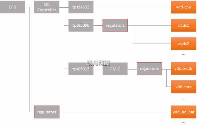
这里的regulator结构是相当复杂的,其中彩色框代表最终的regulator抽象,它的前一级表示regulator的载体(可以是PMIC、CPU、等等)。下面将会详细说明:
a)CPU通过I2C controller,连接一个降压控制器(TI tps51632),该控制器输出名称为“vdd-cpu”的电压,就称作vdd-cpu regulator吧(因此,在kernel中,regulator是一个虚拟设备)。
b)CPU通过I2C controller,连接一个前端电源管理芯片(TI tps65090),该芯片除了具备充电管理功能外,内置了多个regulator,例如dcdc1、dcdc2等等。
c)CPU通过I2C controller,连接另一个电源管理芯片(TI tps65913),该芯片具有两个功能:GPIO输出和PMIC。PMIC内置了多个regulator,如vddio-ddr、vdd-core等等。
d)CPU内部也集成了一些regulator,如vdd_ac_bat等等。
这些思考在本文的例子(NVIDIA Tegra Dalmore A04的regulator)中体现尤为突出,它的本质是软件设计中的模块划分,从而决定了regulator在DTS中的呈现方式和层次。
2.2 使用DTS,将硬件拓扑呈现出来
1)tps51632(是一种电源管理模块)
tps51632是一个简单的器件,位于i2c总线下面,包含一个regulator器件,因此其DTS比较简单,如下:
- : /* arch\arm\boot\dts\tegra114-dalmore.dts */
- : i2c@7000d000 {
- : status = "okay";
- : clock-frequency = <>;
- :
- : tps51632@ {
- : compatible = "ti,tps51632";
- : reg = <0x43>;
- : regulator-name = "vdd-cpu";
- : regulator-min-microvolt = <>;
- : regulator-max-microvolt = <>;
- : regulator-boot-on;
- : regulator-always-on;
- : };
- : ...
- : }
i2c控制器的node为“i2c@7000d000”,tps51632是其下的一个子node,名称为“tps51632@43”,compatible为“ti,tps51632”。tps51632下面以“regulator-”为前缀的字段,是regulator特有的字段,后面会统一介绍。
注2:为什么“i2c@7000d000”中没有compatible字段?其实是有的,可参考“arch\arm\boot\dts\tegra114.dtsi”,DTC在编译DTS时,会将这两个文件中的node合并。
注3:kernel在初始化时,只会为二级node(即“/”下面的节点,本文的例子是“i2c@7000d000”)创建platform设备,至于三级node(这里的“tps51632@43”),则由其bus(i2c)创建。后面我们会遇到其它的情况,到时再介绍。
2)tps65090
tps65090相对比较复杂,它位于相同的i2c总线下面,但包含两个相对复杂的功能实体,charger和PMIC,我们看看其DTS怎么写的:
- : i2c@7000d000 {
- : status = "okay";
- : ...
- :
- : tps65090@ {
- : compatible = "ti,tps65090";
- : reg = <0x48>;
- : ...
- :
- : charger: charger {
- : compatible = "ti,tps65090-charger";
- : ti,enable-low-current-chrg;
- : };
- :
- : regulators {
- : tps65090_dcdc1_reg: dcdc1 {
- : regulator-name = "vdd-sys-5v0";
- : regulator-always-on;
- : regulator-boot-on;
- : };
- :
- : tps65090_dcdc2_reg: dcdc2 {
- : regulator-name = "vdd-sys-3v3";
- : regulator-always-on;
- : regulator-boot-on;
- : };
- : ...
- : }
- : }
- : }
和tps51632类似,但它下面又包含了两个子node:charger和regulators。其中charger竟然还有compatible字段。
回忆一下上面“注3”,kernel只会为"i2c@7000d000”创建platform device,“tps65090@48”则由i2c core创建,那么它下面的子node呢?一定是tps65090 driver处理了,感兴趣的读者可以阅读“drivers/mfd/tps65090.c”、“drivers/power/tps65090-charger.c”和“drivers/regulator/tps65090-regulator.c”,这里面还涉及了MFD(multi-function device,多功能设备),很有意思。
回到本文的主题上,虽然这里的regulators没有compatible字段,也会创建相应的platform device(具体可参考“drivers/mfd/tps65090.c”),这从侧面回答了上面的一个思考:从物理范畴,tps65090是一个独立的设备,但它内部有两个功能模块,因此会存在两个platform device。
3)tps65913,和tps65090类似,不再介绍。
4)CPU中的regulator
这一类regulator比较特殊,直接集成在CPU内部,DTS如下:
- : regulators {
- : compatible = "simple-bus";
- : #address-cells = <>;
- : #size-cells = <>;
- :
- : vdd_ac_bat_reg: regulator@ {
- : compatible = "regulator-fixed";
- : reg = <>;
- : regulator-name = "vdd_ac_bat";
- : regulator-min-microvolt = <>;
- : regulator-max-microvolt = <>;
- : regulator-always-on;
- : };
- :
- : dvdd_ts_reg: regulator@ {
- : compatible = "regulator-fixed";
- : reg = <>;
- : regulator-name = "dvdd_ts";
- : regulator-min-microvolt = <>;
- : regulator-max-microvolt = <>;
- : enable-active-high;
- : gpio = <&gpio TEGRA_GPIO(H, ) GPIO_ACTIVE_HIGH>;
- : };
- : ...
- : };
在回到刚才的话题上,kernel只为二级node创建platform device(这里的“regulators”),那三级node(一个个的regulator)呢?没有相对标准的bus帮它们创建怎么办?借助“simple-bus”,具体可以参考of_platform_bus_create(“Device Tree(三):代码分析”)。
另外,这里的例子比较简单,都是fixed regulator,regulator framework core可以帮忙实现fixed类型的regulator的驱动,后面会说明。
2.3 编写与DTS节点对应的driver
这些driver的存在形式是多种多样的,但所做的工作基本类似:
1)初始化regulator的宿主(如上面的tps5163、PMIC、等等),最终的目的是,通过宿主提供的接口,修改regulator的输出。
2)初始化用于描述regulator的静态信息(struct regulator_desc)和动态信息(struct regulator_config),并以这二者为参数,调用regulator_register接口,将regulator注册到kernel中。
3)静态信息中包含regulator的操作函数集(struct regulator_ops),后续regulator的控制,将会由regulator framework core直接调用这些回调函数完成。
4)后面的事情,例如sysfs attribute创建等,就交给regulator framework core了。
3. DTS相关的实现逻辑
3.1 DTS的内容
回忆一下“Linux Regulator Framework(1)_概述”中介绍的machine的主要功能:使用软件语言(struct regulator_init_data),静态的描述regulator在板级的物理现状。对regulator driver而言,DTS主要用于配置regulator的init data。先看一下struct regulator_init_data:
- : /**
- 2: * struct regulator_init_data - regulator platform initialisation data.
- 3: *
- 4: * Initialisation constraints, our supply and consumers supplies.
- 5: *
- 6: * @supply_regulator: Parent regulator. Specified using the regulator name
- 7: * as it appears in the name field in sysfs, which can
- 8: * be explicitly set using the constraints field 'name'.
- 9: *
- 10: * @constraints: Constraints. These must be specified for the regulator to
- 11: * be usable.
- 12: * @num_consumer_supplies: Number of consumer device supplies.
- 13: * @consumer_supplies: Consumer device supply configuration.
- 14: *
- 15: * @regulator_init: Callback invoked when the regulator has been registered.
- 16: * @driver_data: Data passed to regulator_init.
- 17: */
- : struct regulator_init_data {
- : const char *supply_regulator; /* or NULL for system supply */
- :
- : struct regulation_constraints constraints;
- :
- : int num_consumer_supplies;
- : struct regulator_consumer_supply *consumer_supplies;
- :
- : /* optional regulator machine specific init */
- : int (*regulator_init)(void *driver_data);
- : void *driver_data; /* core does not touch this */
- : };
supply_regulator,该regulator的前级regulator,一般在regulator driver中直接指定;
constraints,该regulator的使用限制,由DTS配置,并可以借助regulator core提供的辅助API(regulator_of_get_init_data)自动解析。后面会详细介绍;
num_consumer_supplies、consumer_supplies,使用该regulator的consumer的个数,及其设备名和supply名的map。用于建立consumer设备和regulator之间的关联,后面介绍consumer DTS时再详细说明;
regulator_init,regulator的init回调,由regulator driver提供,并在regulator注册时调用;
driver_data,保存driver的私有数据,并在调用regulator_init时传入。
看来DTS的内容都在struct regulation_constraints中,该结构保存了该regulator所有的物理限制,如下:
- : struct regulation_constraints {
- :
- : const char *name;
- :
- : /* voltage output range (inclusive) - for voltage control */
- : int min_uV;
- : int max_uV;
- :
- : int uV_offset;
- :
- : /* current output range (inclusive) - for current control */
- : int min_uA;
- : int max_uA;
- :
- : /* valid regulator operating modes for this machine */
- : unsigned int valid_modes_mask;
- :
- : /* valid operations for regulator on this machine */
- : unsigned int valid_ops_mask;
- :
- : /* regulator input voltage - only if supply is another regulator */
- : int input_uV;
- :
- : /* regulator suspend states for global PMIC STANDBY/HIBERNATE */
- : struct regulator_state state_disk;
- : struct regulator_state state_mem;
- : struct regulator_state state_standby;
- : suspend_state_t initial_state; /* suspend state to set at init */
- :
- : /* mode to set on startup */
- : unsigned int initial_mode;
- :
- : unsigned int ramp_delay;
- : unsigned int enable_time;
- :
- : /* constraint flags */
- : unsigned always_on:; /* regulator never off when system is on */
- : unsigned boot_on:; /* bootloader/firmware enabled regulator */
- : unsigned apply_uV:; /* apply uV constraint if min == max */
- : unsigned ramp_disable:; /* disable ramp delay */
- : };
3.2 DTS的解析
regulator的DTS信息,可以通过两种方法解析:
1)在regulator注册前,调用of_get_regulator_init_data接口自行解析,该接口的实现如下:
- : struct regulator_init_data *of_get_regulator_init_data(struct device *dev,
- : struct device_node *node)
- : {
- : struct regulator_init_data *init_data;
- :
- : if (!node)
- : return NULL;
- :
- : init_data = devm_kzalloc(dev, sizeof(*init_data), GFP_KERNEL);
- : if (!init_data)
- : return NULL; /* Out of memory? */
- :
- : of_get_regulation_constraints(node, &init_data);
- : return init_data;
- : }
- : EXPORT_SYMBOL_GPL(of_get_regulator_init_data);
该接口有两个输入参数:设备指针,以及包含了DTS信息的node指针(以3.1中的例子,即“tps51632@43”所在的node)。
它会分配一个struct regulator_init_data变量,并调用of_get_regulation_constraints解析DTS,把结果保存在该变量中。
最后返回struct regulator_init_data变量的地址。
2)在regulator注册时,由regulator_register调用regulator_of_get_init_data帮忙解析,该接口的实现如下:
- : struct regulator_init_data *regulator_of_get_init_data(struct device *dev,
- : const struct regulator_desc *desc,
- : struct device_node **node)
- : {
- : struct device_node *search, *child;
- : struct regulator_init_data *init_data = NULL;
- : const char *name;
- :
- : if (!dev->of_node || !desc->of_match)
- : return NULL;
- :
- : if (desc->regulators_node)
- : search = of_get_child_by_name(dev->of_node,
- : desc->regulators_node);
- : else
- : search = dev->of_node;
- :
- : if (!search) {
- : dev_dbg(dev, "Failed to find regulator container node '%s'\n",
- : desc->regulators_node);
- : return NULL;
- : }
- :
- : for_each_child_of_node(search, child) {
- : name = of_get_property(child, "regulator-compatible", NULL);
- : if (!name)
- : name = child->name;
- :
- : if (strcmp(desc->of_match, name))
- : continue;
- :
- : init_data = of_get_regulator_init_data(dev, child);
- : if (!init_data) {
- : dev_err(dev,
- : "failed to parse DT for regulator %s\n",
- : child->name);
- : break;
- : }
- :
- : of_node_get(child);
- : *node = child;
- : break;
- : }
- : of_node_put(search);
- :
- : return init_data;
- : }
与of_get_regulator_init_data不同的是,该接口以struct regulator_desc指针为参数,该参数提供了regulator DTS有关的搜索信息(desc->of_match),根据这些信息,可以获得包含regulator信息的DTS node。
它本质上是一种通用的DTS匹配逻辑(和kernel解析platform device的标准资源类似),大致如下:
a)调用者提供parent node(struct device指针中,代表regulators的宿主设备,如上面的tps65090@48),以及该regulator在DTS中的名称(由desc->of_match提供)。
b)还可以在struct regulator_desc中提供包含regulator DTS信息的node名称(可选,用于regulator不直接在parent node下的情况)。
c)以parent device的node,或者指定的子node为基准,查找其下所有的node,如果node的名字或者“regulator-compatible”字段和desc->of_match匹配,则调用of_get_regulator_init_data从中解析DTS信息。
总结:1、2两种DTS解析的方法,各有优缺点:1直接,方便,容易理解,但会有冗余代码;2简洁,但需要regulator driver开发者非常熟悉解析的原理,并以此设计DTS和struct regulator_desc变量。大家可以根据实际情况,灵活使用。
4. 主要数据结构
4.1 struct regulator_desc
- : /* include/linux/regulator/driver.h */
- :
- : struct regulator_desc {
- : const char *name;
- : const char *supply_name;
- : const char *of_match;
- : const char *regulators_node;
- : int id;
- : bool continuous_voltage_range;
- : unsigned n_voltages;
- : const struct regulator_ops *ops;
- : int irq;
- : enum regulator_type type;
- : struct module *owner;
- :
- : unsigned int min_uV;
- : unsigned int uV_step;
- : unsigned int linear_min_sel;
- : int fixed_uV;
- : unsigned int ramp_delay;
- :
- : const struct regulator_linear_range *linear_ranges;
- : int n_linear_ranges;
- :
- : const unsigned int *volt_table;
- :
- : unsigned int vsel_reg;
- : unsigned int vsel_mask;
- : unsigned int apply_reg;
- : unsigned int apply_bit;
- : unsigned int enable_reg;
- : unsigned int enable_mask;
- : unsigned int enable_val;
- : unsigned int disable_val;
- : bool enable_is_inverted;
- : unsigned int bypass_reg;
- : unsigned int bypass_mask;
- : unsigned int bypass_val_on;
- : unsigned int bypass_val_off;
- :
- : unsigned int enable_time;
- :
- : unsigned int off_on_delay;
- : };
4.2 struct regulator_config
struct regulator_config保存了regulator的动态信息,所谓的动态信息,是指那些会在driver运行过程中改变、或者driver运行后才会确定的信息,如下:
- : struct regulator_config {
- : struct device *dev;
- : const struct regulator_init_data *init_data;
- : void *driver_data;
- : struct device_node *of_node;
- : struct regmap *regmap;
- :
- : int ena_gpio;
- : unsigned int ena_gpio_invert:;
- : unsigned int ena_gpio_flags;
- : };
dev,对应的struct device指针。会在regulator_register时,由regulator core分配,保存在此,以便后续使用;
init_data,init data指针,在解析DTS后,保存在此,以便后续使用;
of_node,可以为空;
regmap,参考后续描述;
ena_gpio、ena_gpio_invert、ena_gpio_flags,控制regulator使能的GPIO及其active极性。
4.3 struct regulator_dev
struct regulator_dev是regulator设备的抽象,当driver以struct regulator_desc、struct regulator_config两个类型的参数,调用regulator_register将regulator注册到kernel之后,regulator就会分配一个struct regulator_dev变量,后续所有的regulator操作,都将以该变量为对象。
- : struct regulator_dev {
- : const struct regulator_desc *desc;
- : int exclusive;
- : u32 use_count;
- : u32 open_count;
- : u32 bypass_count;
- :
- : /* lists we belong to */
- : struct list_head list; /* list of all regulators */
- :
- : /* lists we own */
- : struct list_head consumer_list; /* consumers we supply */
- :
- : struct blocking_notifier_head notifier;
- : struct mutex mutex; /* consumer lock */
- : struct module *owner;
- : struct device dev;
- : struct regulation_constraints *constraints;
- : struct regulator *supply; /* for tree */
- : struct regmap *regmap;
- :
- : struct delayed_work disable_work;
- : int deferred_disables;
- :
- : void *reg_data; /* regulator_dev data */
- :
- : struct dentry *debugfs;
- :
- : struct regulator_enable_gpio *ena_pin;
- : unsigned int ena_gpio_state:;
- :
- : /* time when this regulator was disabled last time */
- : unsigned long last_off_jiffy;
- : };
desc,保存了regulator静态描述信息的指针(从这个角度看,所谓的静态描述,其变量必须为全局变量);
exclusive、use_count、open_count、bypass_count,一些状态记录;
constraints,保存了regulator的constraints指针;
supply,该regulator的supply;
等等。
5 实现逻辑分析
本章简单的分析一下regulator driver相关的实现逻辑。如果要理解有些逻辑,必须具备一些regulator的基础知识,因此在需要的时候,会穿插介绍这些知识。
5.1 regulator core的初始化
regulator core的初始化操作由regulator_init接口负责,主要工作包括:
1)注册regulator class(/sys/class/regulator/)。
2)注册用于调试的debugfs。
和power switch class、input class等类似,regulator framework也是一种class,可以称作regulator class。
5.2 regulator register
regulator的注册,由regulator_register/devm_regulator_register接口负责,如下:
- : /**
- 2: * regulator_register - register regulator
- 3: * @regulator_desc: regulator to register
- 4: * @config: runtime configuration for regulator
- 5: *
- 6: * Called by regulator drivers to register a regulator.
- 7: * Returns a valid pointer to struct regulator_dev on success
- 8: * or an ERR_PTR() on error.
- 9: */
- : struct regulator_dev *
- : regulator_register(const struct regulator_desc *regulator_desc,
- : const struct regulator_config *config)
- : {
- : const struct regulation_constraints *constraints = NULL;
- : const struct regulator_init_data *init_data;
- : static atomic_t regulator_no = ATOMIC_INIT();
- : struct regulator_dev *rdev;
- : struct device *dev;
- : int ret, i;
- : const char *supply = NULL;
- :
- : if (regulator_desc == NULL || config == NULL)
- : return ERR_PTR(-EINVAL);
- :
- : dev = config->dev;
- : WARN_ON(!dev);
- :
- : if (regulator_desc->name == NULL || regulator_desc->ops == NULL)
- : return ERR_PTR(-EINVAL);
- :
- : if (regulator_desc->type != REGULATOR_VOLTAGE &&
- : regulator_desc->type != REGULATOR_CURRENT)
- : return ERR_PTR(-EINVAL);
- :
- : /* Only one of each should be implemented */
- : WARN_ON(regulator_desc->ops->get_voltage &&
- : regulator_desc->ops->get_voltage_sel);
- : WARN_ON(regulator_desc->ops->set_voltage &&
- : regulator_desc->ops->set_voltage_sel);
- :
- : /* If we're using selectors we must implement list_voltage. */
- : if (regulator_desc->ops->get_voltage_sel &&
- : !regulator_desc->ops->list_voltage) {
- : return ERR_PTR(-EINVAL);
- : }
- : if (regulator_desc->ops->set_voltage_sel &&
- : !regulator_desc->ops->list_voltage) {
- : return ERR_PTR(-EINVAL);
- : }
- :
- : rdev = kzalloc(sizeof(struct regulator_dev), GFP_KERNEL);
- : if (rdev == NULL)
- : return ERR_PTR(-ENOMEM);
- :
- : init_data = regulator_of_get_init_data(dev, regulator_desc,
- : &rdev->dev.of_node);
- : if (!init_data) {
- : init_data = config->init_data;
- : rdev->dev.of_node = of_node_get(config->of_node);
- : }
- :
- : mutex_lock(®ulator_list_mutex);
- :
- : mutex_init(&rdev->mutex);
- : rdev->reg_data = config->driver_data;
- : rdev->owner = regulator_desc->owner;
- : rdev->desc = regulator_desc;
- : if (config->regmap)
- : rdev->regmap = config->regmap;
- : else if (dev_get_regmap(dev, NULL))
- : rdev->regmap = dev_get_regmap(dev, NULL);
- : else if (dev->parent)
- : rdev->regmap = dev_get_regmap(dev->parent, NULL);
- : INIT_LIST_HEAD(&rdev->consumer_list);
- : INIT_LIST_HEAD(&rdev->list);
- : BLOCKING_INIT_NOTIFIER_HEAD(&rdev->notifier);
- : INIT_DELAYED_WORK(&rdev->disable_work, regulator_disable_work);
- :
- : /* preform any regulator specific init */
- : if (init_data && init_data->regulator_init) {
- : ret = init_data->regulator_init(rdev->reg_data);
- : if (ret < )
- : goto clean;
- : }
- :
- : /* register with sysfs */
- : rdev->dev.class = ®ulator_class;
- : rdev->dev.parent = dev;
- : dev_set_name(&rdev->dev, "regulator.%d",
- : atomic_inc_return(®ulator_no) - );
- : ret = device_register(&rdev->dev);
- : if (ret != ) {
- : put_device(&rdev->dev);
- : goto clean;
- : }
- :
- : dev_set_drvdata(&rdev->dev, rdev);
- :
- : if (config->ena_gpio && gpio_is_valid(config->ena_gpio)) {
- : ret = regulator_ena_gpio_request(rdev, config);
- : if (ret != ) {
- : rdev_err(rdev, "Failed to request enable GPIO%d: %d\n",
- : config->ena_gpio, ret);
- : goto wash;
- : }
- :
- : if (config->ena_gpio_flags & GPIOF_OUT_INIT_HIGH)
- : rdev->ena_gpio_state = ;
- :
- : if (config->ena_gpio_invert)
- : rdev->ena_gpio_state = !rdev->ena_gpio_state;
- : }
- :
- : /* set regulator constraints */
- : if (init_data)
- : constraints = &init_data->constraints;
- :
- : ret = set_machine_constraints(rdev, constraints);
- : if (ret < )
- : goto scrub;
- :
- : /* add attributes supported by this regulator */
- : ret = add_regulator_attributes(rdev);
- : if (ret < )
- : goto scrub;
- :
- : if (init_data && init_data->supply_regulator)
- : supply = init_data->supply_regulator;
- : else if (regulator_desc->supply_name)
- : supply = regulator_desc->supply_name;
- :
- : if (supply) {
- : struct regulator_dev *r;
- :
- : r = regulator_dev_lookup(dev, supply, &ret);
- :
- : if (ret == -ENODEV) {
- : /*
- 139: * No supply was specified for this regulator and
- 140: * there will never be one.
- 141: */
- : ret = ;
- : goto add_dev;
- : } else if (!r) {
- : dev_err(dev, "Failed to find supply %s\n", supply);
- : ret = -EPROBE_DEFER;
- : goto scrub;
- : }
- :
- : ret = set_supply(rdev, r);
- : if (ret < )
- : goto scrub;
- :
- : /* Enable supply if rail is enabled */
- : if (_regulator_is_enabled(rdev)) {
- : ret = regulator_enable(rdev->supply);
- : if (ret < )
- : goto scrub;
- : }
- : }
- :
- : add_dev:
- : /* add consumers devices */
- : if (init_data) {
- : for (i = ; i < init_data->num_consumer_supplies; i++) {
- : ret = set_consumer_device_supply(rdev,
- : init_data->consumer_supplies[i].dev_name,
- : init_data->consumer_supplies[i].supply);
- : if (ret < ) {
- : dev_err(dev, "Failed to set supply %s\n",
- : init_data->consumer_supplies[i].supply);
- : goto unset_supplies;
- : }
- : }
- : }
- :
- : list_add(&rdev->list, ®ulator_list);
- :
- : rdev_init_debugfs(rdev);
- : out:
- : mutex_unlock(®ulator_list_mutex);
- : return rdev;
- :
- : unset_supplies:
- : unset_regulator_supplies(rdev);
- :
- : scrub:
- : if (rdev->supply)
- : _regulator_put(rdev->supply);
- : regulator_ena_gpio_free(rdev);
- : kfree(rdev->constraints);
- : wash:
- : device_unregister(&rdev->dev);
- : /* device core frees rdev */
- : rdev = ERR_PTR(ret);
- : goto out;
- :
- : clean:
- : kfree(rdev);
- : rdev = ERR_PTR(ret);
- : goto out;
- : }
- : EXPORT_SYMBOL_GPL(regulator_register);
主要工作包括:
22~49,检查参数的合法性。其中35~49行,涉及到电压控制的方式,后面后详细说明;
55~60,协助从DTS解析init data,如果解析不到,则使用config中的;
68~73,协助获取regulator的register map(有的话),并保存在register device指针中。regulator driver会在需要的时候使用(通常是在ops回调函数中);
74~77,初始化一些全局变量,consumer_list用于保存所有的consumer,list用于将自己添加到一个全局的regulator链表(regulator_list)上,disable_work是用于disable regulator的work queue;
86~95,将regulator device注册到kernel;
99~112,申请regulator enable gpio(有的话),并将相应的信息保存在regulator device指针中;
114~120,将从DTS中解析的constraints,应用起来(这个过程比较复杂,就不介绍了,感兴趣的读者可以自行分析);
123,根据regulator的操作函数集,注册相应的attribute(和PSY class类似);
127~160,如果该regulator有supply,根据supply的名字,获取相应的regulator device指针,同时根据supply指针,分配一个struct regulator结构,保存在该regulator的supply指针中。最后,如果该regulator处于使能状态,则需要使能其supply(这些动作,需要以consumer的视角操作,因而需要一个struct regulator变量);
162~175,add consumer devices,等到介绍consumer时,再详细描述。
注4:register map是kernel提供的一种管理寄存器的机制,特别是较为复杂的寄存器,如codec等。本文不会过多描述,如需要,会专门写一篇文章介绍该机制。
5.3 regulator的操作模式(operation mode)
regulator的主要功能,是输出电压/电流的调整(或改变)。由于模拟器件的特性,电压/电流的改变,是需要一定的时间的。对有些regulator而言,可以工作在不同的模式,这些模式有不同的改变速度,可想而知,较快的速度,有较大的功耗。下面是operation mode定义(位于include/linux/regulator/consumer.h中):
- : /*
- 2: * Regulator operating modes.
- 3: *
- 4: * Regulators can run in a variety of different operating modes depending on
- 5: * output load. This allows further system power savings by selecting the
- 6: * best (and most efficient) regulator mode for a desired load.
- 7: *
- 8: * Most drivers will only care about NORMAL. The modes below are generic and
- 9: * will probably not match the naming convention of your regulator data sheet
- 10: * but should match the use cases in the datasheet.
- 11: *
- 12: * In order of power efficiency (least efficient at top).
- 13: *
- 14: * Mode Description
- 15: * FAST Regulator can handle fast changes in it's load.
- 16: * e.g. useful in CPU voltage & frequency scaling where
- 17: * load can quickly increase with CPU frequency increases.
- 18: *
- 19: * NORMAL Normal regulator power supply mode. Most drivers will
- 20: * use this mode.
- 21: *
- 22: * IDLE Regulator runs in a more efficient mode for light
- 23: * loads. Can be used for devices that have a low power
- 24: * requirement during periods of inactivity. This mode
- 25: * may be more noisy than NORMAL and may not be able
- 26: * to handle fast load switching.
- 27: *
- 28: * STANDBY Regulator runs in the most efficient mode for very
- 29: * light loads. Can be used by devices when they are
- 30: * in a sleep/standby state. This mode is likely to be
- 31: * the most noisy and may not be able to handle fast load
- 32: * switching.
- 33: *
- 34: * NOTE: Most regulators will only support a subset of these modes. Some
- 35: * will only just support NORMAL.
- 36: *
- 37: * These modes can be OR'ed together to make up a mask of valid register modes.
- 38: */
- :
- : #define REGULATOR_MODE_FAST 0x1
- : #define REGULATOR_MODE_NORMAL 0x2
- : #define REGULATOR_MODE_IDLE 0x4
- : #define REGULATOR_MODE_STANDBY 0x8
相应的,regulator framework提供了一些机制,用于operation mode的操作,包括:
1)struct regulation_constraints中用于表示初始模式的字段initial_mode。
2)regulator ops中的set_mode/get_mode回调函数。
5.4 电压操作的两种方式
kernel抽象了两种电压操作的方法:
1)直接操作电压,对应struct regulator_ops中的如下回调函数:
- : /* get/set regulator voltage */
- : int (*list_voltage) (struct regulator_dev *, unsigned selector);
- : int (*set_voltage) (struct regulator_dev *, int min_uV, int max_uV,
- : unsigned *selector);
- : int (*get_voltage) (struct regulator_dev *);
其中set_voltage用于将电压设置为min_uV和max_uV范围内、和min_uV最接近的电压。该接口可以返回一个selector参数,用于告知调用者,实际的电压值;
get_voltage,用于返回当前的电压值;
list_voltage,以selector为参数,获取对应的电压值。
注5:有关selector的描述,可参考下面的介绍。
2)selector的形式
regulator driver以selector的形式,反映电压值。selector是一个从0开始的整数,driver提供如下的接口:
- : /* enumerate supported voltages */
- : int (*list_voltage) (struct regulator_dev *, unsigned selector);
- :
- : int (*map_voltage)(struct regulator_dev *, int min_uV, int max_uV);
- : int (*set_voltage_sel) (struct regulator_dev *, unsigned selector);
- : int (*get_voltage_sel) (struct regulator_dev *);
list_voltage,上面已经介绍;
map_voltage,是和list_voltage相对的接口,用于将电压范围map成一个selector值;
set_voltage_sel/get_voltage_sel,以selector的形式,操作电压。
regulator driver可以根据实际情况,选择一种实现方式。
5.5 regulator framework提供的sysfs接口
根据regulator提供的ops情况,regulator framework可以通过sysfs提供多种attribute,它们位于/sys/class/regulator/.../目录下,数量相当多,这里就不一一描述了,具体可参考:
https://www.kernel.org/doc/Documentation/ABI/testing/sysfs-class-regulator
6. 后记
这篇文章写的相当纠结,相当混乱,我相信读者很难看懂……
Linux Regulator Framework(2)_regulator driver的更多相关文章
- Linux regulator framework(1) - 概述【转】
转自蜗窝科技:http://www.wowotech.net/pm_subsystem/regulator_framework_overview.html 1. 前言 Regulator,中文名翻译为 ...
- Linux电源管理-Linux regulator framework概述
前言 1. 什么是regulator? regulator翻译为"调节器",分为voltage regulator(电压调节器)和current(电流调节器).一般电源 ...
- Linux PWM framework简介和API描述【转】
本文转载自:https://blog.csdn.net/mike8825/article/details/51656400 1. 前言 PWM是Pulse Width Modulation(脉冲宽度调 ...
- Linux regulator系统
1. 概念:Regulator : 电源芯片, 比如电压转换芯片Consumer : 消费者,使用电源的部件, Regulator是给Consumer供电的machine : 单板,上面焊接有Regu ...
- 【原创】Linux cpufreq framework
背景 Read the fucking source code! --By 鲁迅 A picture is worth a thousand words. --By 高尔基 说明: Kernel版本: ...
- 【原创】Linux cpuidle framework
背景 Read the fucking source code! --By 鲁迅 A picture is worth a thousand words. --By 高尔基 说明: Kernel版本: ...
- Linux Thermal Framework分析及实施
关键词:Zone.Cooling.Governor.Step Wise.Fair Share.trip等等. Linux Thermal的目的是控制系统运行过程中采样点温度,避免温度过高造成器件损坏, ...
- Linux kernel support docker storage driver aufs
How to make docker use aufs in CentOS 7? - Server Faulthttps://serverfault.com/questions/650208/how- ...
- linux regulator之浅见【转】
转自:http://blog.csdn.net/batoom/article/details/17081651 1: 校准器的基本概念 所谓校准器实际是在软件控制下把输入的电源调节精心输出. Regu ...
随机推荐
- numpy中pad函数的常用方法
一.参数解释 ndarray = numpy.pad(array, pad_width, mode, **kwargs) array为要填补的数组 pad_width是在各维度的各个方向上想要填补的长 ...
- Docker总结(脑图图片)
- Ubuntu编译安装最新的webkit
好久都没更新webkit 源码在ubuntu上编译了,网上搜了一下,基本上都是早期编译的webkit版本.可能是大家都去搞高大上的谷歌浏览器了吧. 今天就以ubuntu14.04版本作为编译环境来讲讲 ...
- salesforce lightning零基础学习(八) Aura Js 浅谈一: Component篇
我们在开发lightning的时候,常常会在controller.js中写 component.get('v.label'), component.set('v.label','xxValue'); ...
- android ART hook
0x00 前言 之前一直都是在Dalvik 虚拟机上在折腾,从Android 4.4开始开始引入ART,到5.0已经成为默认选择.而且最近看到阿里开源的 Dexposed 框架,已经提供了对于andr ...
- Haproxy+Heartbeat 高可用集群方案操作记录
之前详细介绍了haproxy的基础知识点, 下面记录下Haproxy+Heartbeat高可用web集群方案实现过程, 以加深理解. 架构草图如下: 1) 基本环境准备 (centos6.9系统) 1 ...
- delete attempted to return null from a method with a primitive return type (int)
今天被自己给蠢死了 今天在代码中遇到这个错误, 百度翻译一下:映射方法,从一org.system.mapper.child.chmorganizationexaminationmapper.delet ...
- 三、TortoiseGit之配置密钥
TortoiseGit使用扩展名为ppk的密钥,而不是ssh-keygen生成的rsa密钥. 也就是说使用 ssh-keygen -t rsa -C "username@email.co ...
- SpringMVC入门学习(一)
SpringMVC入门学习(一) ssm框架 spring SpringMVC是一个Java WEB框架,现在我们知道Spring了,那么,何为MVC呢? MVC是一种设计模式,其分为3个方面 mo ...
- Django之模型层(多表操作)
一.创建模型 1,一对多关系 一本书只有一个出版社,一个出版社可以出版多本书,从而书与出版社之间就构成一对多关系,书是‘多’的一方,出版社是‘一’的一方,我们在建立模型的时候,把外键写在‘多’的一方, ...