16C554(8250)驱动分析
参考:
http://www.cnblogs.com/zym0805/p/4815041.html
一. 硬件数据手册
The ST16C554D is a universal asynchronous receiver and transmitter (UART) with a dual foot print interface.
The 554D is an enhanced UART with 16 byte FIFOs, receive trigger levels and data rates up to 1.5Mbps.
The 554D is available in 64 pin TQFP, and 68 pin PLCC packages. The 68 pin PLCC package offer an additional 68 mode which allows easy integration with Motorola, and other popular microprocessors.
The 554D combines the package interface modes of the 16C554D and 68C554 series on a single integrated chip. The 16 mode interface is designed to operate with the Intel type of microprocessor bus while the 68 mode is intended to operate with Motorola, and other popular microprocessors. Following a reset, the 554D is down-ward compatible with the ST16C454/ST68C454 dependent on the state of the interface mode selection pin, 16/-68.
共有两种总线接口:16mode(Intel)和68mode(Motorola),板卡上用用ST16C554DIQ64,仅支持16mode。
PIN介绍
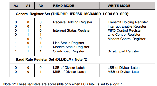
A0/A1/A2: Address-0/1/2 Select Bit. Internal registers address selection in 16 and 68 modes.
-CS:This pin is not available on 64 pin packages which operate in the 16 mode only.
-CSA/B/C/D:Chip Select A, B, C, D (active low) - This function is associated with the 16 mode only, and for individual channels, “A” through “D.”
INTA/B/C/D:Interrupt A, B, C, D (active high) - This function is associated with the 16 mode only. These pins provide individual channel interrupts, INT A-D. INT A-D are enabled when MCR bit-3 is set to a logic 1, interrupts are enabled in the interrupt enable register (IER), and when an interrupt condition exists. Interrupt conditions include: receiver errors, available receiver buffer data, transmit buffer empty, or when a modem status flag is detected. When the 68 mode is selected, the functions of these pins are reassigned. 68 mode functions are described under the their respective name/pin headings.
寄存器
The 554D provides 13 internal registers for monitoring and control.
FIFO
The 16 byte transmit and receive data FIFO’s are enabled by the FIFO Control Register (FCR) bit-0. With 16C554 devices, the user can only set the receive trigger level. The receiver FIFO section includes a time-out function to ensure data is delivered to the external CPU. An interrupt is generated whenever the Receive Holding Register (RHR) has not been read following the loading of a character or the receive trigger level has not been reached.
Interrupts
The interrupts are enabled by IER bits 0-3. Care must be taken when handling these interrupts. Following a reset the transmitter interrupt is enabled, the 554D will issue an interrupt to indicate that transmit holding register is empty. This interrupt must be serviced prior to continuing operations. The LSR register provides the current singular highest priority interrupt only. Servicing the interrupt without investigating further interrupt conditions can result in data errors.
When two interrupt conditions have the same priority, it is important to service these interrupts correctly. Receive Data Ready and Receive Time Out have the same interrupt priority (when enabled by IER bit-0).The receiver issues an interrupt after the number of characters have reached the programmed trigger level. In this case the 554D FIFO may hold more characters than the programmed trigger level. Following the removal of a data byte, the user should recheck LSR bit-0 for additional characters. A Receive Time Out will not occur if the receive FIFO is empty. The time out counter is reset at the center of each stop bit received or each time the receive holding register (RHR) is read.
DMA
LSR bits 5-6 provide an indication when the transmitter is empty or has an empty location(s). The user can optionally operate the transmit and receive FIFOs in the DMA mode (FCR bit-3). When the transmit and receive FIFOs are enabled and the DMA mode is deactivated (DMA Mode “0”), the 554D activates the interrupt output pin for each data transmit or receive operation. When DMA mode is activated (DMA Mode “1”), the user takes the advantage of block mode operation by loading or unloading the FIFO in a block sequence determined by the preset trigger level. In this mode, the 554D sets the interrupt output pin when characters in the transmit FIFOs are below the transmit trigger level, or the characters in the receive FIFOs are above the receive trigger level.
Interrupt Enable Register (IER)
The Interrupt Enable Register (IER) masks the interrupts from receiver ready, transmitter empty, line status and modem status registers. These interrupts would normally be seen on the INT A-D output pins in the 16 mode, or on WIRE-OR IRQ output pin, in the 68 mode.
IER BIT-0: This interrupt will be issued when the FIFO has reached the programmed trigger level or is cleared when the FIFO drops below the trigger level in the FIFO mode of operation.
Logic 0 = Disable the receiver ready interrupt. (normal default condition)
Logic 1 = Enable the receiver ready interrupt.
Interrupt Status Register (ISR)
The 554D provides four levels of prioritized interrupts to minimize external software interaction. The Interrupt Status Register (ISR) provides the user with six interrupt status bits. Performing a read cycle on the ISR will provide the user with the highest pending interrupt level to be serviced. No other interrupts are acknowledged until the pending interrupt is serviced. Whenever the interrupt status register is read, the interrupt status is cleared. However it should be noted that only the current pending interrupt is cleared by the read. A lower level interrupt may be seen after rereading the interrupt status bits. The Interrupt Source Table 7 (below) shows the data values (bit 0-5) for the four prioritized interrupt levels and the interrupt sources associated with each of these interrupt levels:

16C554(8250)驱动分析的更多相关文章
- [tty与uart]3.tty驱动分析
转自:http://www.wowotech.net/linux_kenrel/183.html 目录: 1 首先分析设备驱动的注册 1.1 uart_register_driver分析 1.2 tt ...
- linux串口驱动分析
linux串口驱动分析 硬件资源及描写叙述 s3c2440A 通用异步接收器和发送器(UART)提供了三个独立的异步串行 I/O(SIO)port,每一个port都能够在中断模式或 DMA 模式下操作 ...
- Linux 串口、usb转串口驱动分析(2-2) 【转】
转自:http://blog.chinaunix.net/xmlrpc.php?r=blog/article&uid=26807463&id=4186852 Linux 串口.usb转 ...
- Linux 串口、usb转串口驱动分析(2-1) 【转】
转自:http://blog.chinaunix.net/xmlrpc.php?r=blog/article&uid=26807463&id=4186851 Linux 串口.usb转 ...
- [uart]3.tty驱动分析
转自:http://www.wowotech.net/linux_kenrel/183.html 目录: 1 首先分析设备驱动的注册 1.1 uart_register_driver分析 1.2 tt ...
- linux驱动基础系列--Linux 串口、usb转串口驱动分析
前言 主要是想对Linux 串口.usb转串口驱动框架有一个整体的把控,因此会忽略某些细节,同时里面涉及到的一些驱动基础,比如字符设备驱动.平台驱动等也不进行详细说明原理.如果有任何错误地方,请指出, ...
- Linux UART驱动分析
1. 介绍 8250是IBM PC及兼容机使用的一种串口芯片; 16550是一种带先进先出(FIFO)功能的8250系列串口芯片; 16550A则是16550的升级版本, 修复了FIFO相关BUG, ...
- linux的串口驱动分析
1.串口驱动中的数据结构 • UART驱动程序结构:struct uart_driver 驱动 • UART端口结构: struct uart_port 串口 • UART相关操作函数结构: st ...
- linux内核SPI总线驱动分析(一)(转)
linux内核SPI总线驱动分析(一)(转) 下面有两个大的模块: 一个是SPI总线驱动的分析 (研究了具体实现的过程) 另一个是SPI总线驱动的编写(不用研究具体的实现过程) ...
- Mini2440 DM9000 驱动分析(一)
Mini2440 DM9000 驱动分析(一) 硬件特性 Mini2440开发板上DM9000的电气连接和Mach-mini2440.c文件的关系: PW_RST 连接到复位按键,复位按键按下,低电平 ...
随机推荐
- 8.Java格式化输出
JAVA中字符串输出格式 1.使用format函数 System.out.format("%d %f",10,10.5); 2.使用Formatter类 构造函数Formatte ...
- 基于命令行编译打包phonegap for android应用 分类: Android Phonegap 2015-05-10 10:33 73人阅读 评论(0) 收藏
也许你习惯了使用Eclipse编译和打包Android应用.不过,对于使用html5+js开发的phonegap应用,本文建议你抛弃Eclipse,改为使用命令行模式,绝对的快速和方便. 一直以来,E ...
- windows 10 设置
精简应用 邮件和日历: Get-AppxPackage *communi* | Remove-AppxPackage 新闻: Get-AppxPackage *bing* | Remove-AppxP ...
- CodeTimerPerformance EasyPerformanceCounterHelper .NET 4.5
//#define NET35 namespace TestConsoleApplication { using System; using System.Diagnostics; using Sys ...
- include、merge 、ViewStub
在布局优化中,Androi的官方提到了这三种布局<include />.<merge />.<ViewStub />,并介绍了这三种布局各有的优势,下面也是简单说一 ...
- Android开发各类常见错误解决方案
本文属于个人平时项目开发过程遇到的一些问题,记录下来并总结解决方案,希望能帮到大家解决问题,有些问题的解决方案是在StackoverFlow上找到的,建议大家遇到问题多去上面找,基本上都能找到解决方案 ...
- java发送GET和post请求
package com.baqingshe.bjs.util; import java.io.BufferedReader; import java.io.IOException; import ja ...
- hdu 3632 A Captivating Match(区间dp)
题目链接:http://acm.split.hdu.edu.cn/showproblem.php?pid=3632 题意:n个人进行比赛,每个人有一个价值a[i],最后冠军只有一个,只能相邻两个人进行 ...
- Codeforces Round #353 (Div. 2)
数学 A - Infinite Sequence 等差数列,公差是0的时候特判 #include <bits/stdc++.h> typedef long long ll; const i ...
- iOS 单例模式范例
The singleton pattern is useful for creating objects that are shared across the entire application, ...