STM32输入捕获模式设置并用DMA接收数据
参考: STM32的PWM输入模式设置并用DMA接收数据
Input capture mode
The input stage samples the corresponding TIx input to generate a filtered signal TIxF.
Then, an edge detector with polarity selection generates a signal (TIxFPx)
which can be used as trigger input by the slave mode controller or as the capture command.
It is prescaled before the capture register (ICxPS).
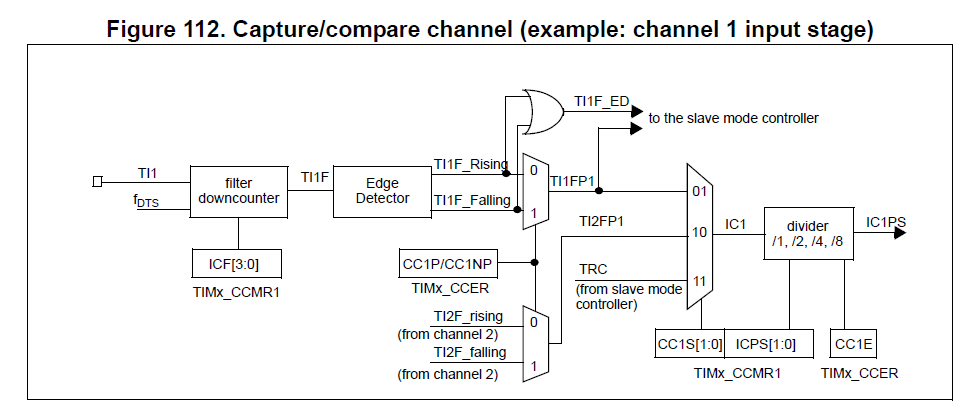
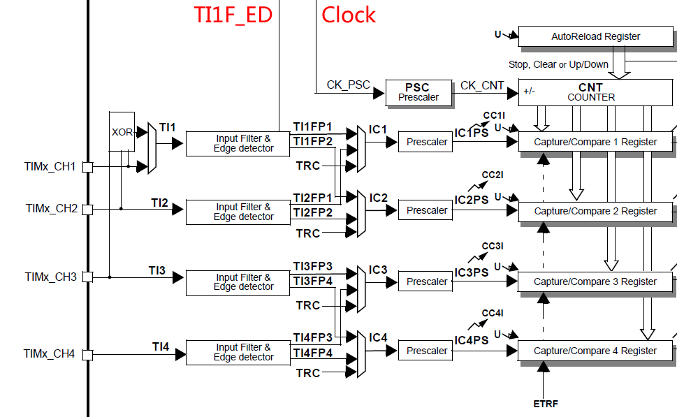
In Input capture mode, the Capture/Compare Registers (TIMx_CCRx) are used to latch the value of the counter
after a transition detected by the corresponding ICx signal.
When a capture occurs, the corresponding CCXIF flag (TIMx_SR register) is set and an interrupt
or a DMA request can be sent if they are enabled.
If a capture occurs while the CCxIF flag was already high, then the over-capture flag CCxOF (TIMx_SR register) is set.
CCxIF can be cleared by software by writing it to ‘0’ or by reading the captured data stored in the TIMx_CCRx register.
CCxOF is cleared when you write it to ‘0’.
The following example shows how to capture the counter value in TIMx_CCR1 when TI1 input rises.
To do this, use the following procedure:
Select the active input:
TIMx_CCR1 must be linked to the TI1 input, so write the CC1S bits to 01 in the TIMx_CCMR1 register.
As soon as CC1S becomes different from 00, the channel is configured in input and the TIMx_CCR1 register becomes read-only.
Program the input filter duration you need with respect to the signal you connect to the timer
(by programming ICxF bits in the TIMx_CCMRx register if the input is a TIx input).
Let’s imagine that, when toggling, the input signal is not stable during at must 5 internal clock cycles.
We must program a filter duration longer than these 5 clock cycles.
We can validate a transition on TI1 when 8 consecutive samples with the new level have been detected (sampled at fDTS frequency).
Then write IC1F bits to 0011 in the TIMx_CCMR1 register.
Select the edge of the active transition on the TI1 channel by writing CC1P and CC1NP bits to 0
in the TIMx_CCER register (rising edge in this case).
Program the input prescaler. In our example, we wish the capture to be performed at each valid transition,
so the prescaler is disabled (write IC1PS bits to ‘00’ in the TIMx_CCMR1 register).
Enable capture from the counter into the capture register by setting the CC1E bit in the TIMx_CCER register.
If needed, enable the related interrupt request by setting the CC1IE bit in the TIMx_DIER register,
and/or the DMA request by setting the CC1DE bit in the TIMx_DIER register.
When an input capture occurs:
The TIMx_CCR1 register gets the value of the counter on the active transition.
CC1IF flag is set (interrupt flag). CC1OF is also set if at least two consecutive captures occurred whereas the flag was not cleared.
An interrupt is generated depending on the CC1IE bit.
A DMA request is generated depending on the CC1DE bit.
In order to handle the overcapture, it is recommended to read the data before the overcapture flag.
This is to avoid missing an overcapture which could happen after reading the flag and before reading the data.
Note:
IC interrupt and/or DMA requests can be generated by software by setting the corresponding CCxG bit in the TIMx_EGR register.
STM32输入捕获模式设置并用DMA接收数据
本文博客链接:http://blog.csdn.net/jdh99,作者:jdh
环境:
主机:WIN7
开发环境:MDK4.72
MCU:STM32F103
说明:
项目中需要进行红外学习,于是采用输入捕获取得电平变化时间.并将数据放在DMA中.这样可以避免频繁中断消耗CPU资源.
采用的是PB1脚,对应TIM3的通道4.
/*********************************************************************

*                            接口函数:初始化红外学习模块

**********************************************************************/

void inf_infrared_study_init(void)

{

    //初始化io口

      inf_init_io();

    //初始化中断

    //inf_init_irq();

    //初始化定时器

    inf_init_timer();

    //打开DMA

    inf_infrared_study_open_dma();

    //打开定时器

    inf_infrared_study_open_timer();

}

/*********************************************************************

*                            初始化io口

**********************************************************************/

static void inf_init_io(void)

{

    //定义IO初始化结构体

    GPIO_InitTypeDef GPIO_InitStructure;

    //初始化时钟

    RCC_APB2PeriphClockCmd(RCC_APB2Periph_GPIOB,ENABLE);

    //管脚初始化

    GPIO_InitStructure.GPIO_Pin = GPIO_Pin_1;

    //设置为输入

    GPIO_InitStructure.GPIO_Mode = GPIO_Mode_IN_FLOATING;

    //初始化

    GPIO_Init(GPIOB, &GPIO_InitStructure);

}

/*********************************************************************

*                            初始化中断

**********************************************************************/

static void inf_init_irq(void)

{

    //定义外部中断结构体

    EXTI_InitTypeDef EXTI_InitStructure;

    //初始化中断脚复用时钟

    RCC_APB2PeriphClockCmd(RCC_APB2Periph_AFIO,ENABLE);

    //配置中断源

    GPIO_EXTILineConfig(GPIO_PortSourceGPIOB,GPIO_PinSource1);

    // 配置下降沿触发

    EXTI_ClearITPendingBit(EXTI_Line1);

    EXTI_InitStructure.EXTI_Line = EXTI_Line1;

    EXTI_InitStructure.EXTI_Trigger = EXTI_Trigger_Falling;

    EXTI_InitStructure.EXTI_Mode = EXTI_Mode_Interrupt;

    EXTI_InitStructure.EXTI_LineCmd = ENABLE;

    EXTI_Init(&EXTI_InitStructure);

}

/*********************************************************************

*                            初始化定时器

**********************************************************************/

static void inf_init_timer(void)

{

    //定义定时器结构体

    TIM_TimeBaseInitTypeDef timInitStruct;

    //输入捕获结构体

    TIM_ICInitTypeDef tim_icinit;

    //定义DMA结构体

    DMA_InitTypeDef DMA_InitStructure;

    //启动DMA时钟

    RCC_AHBPeriphClockCmd(RCC_AHBPeriph_DMA1, ENABLE);

    //DMA1通道3配置

    DMA_DeInit(DMA1_Channel3);

    //外设地址

    DMA_InitStructure.DMA_PeripheralBaseAddr = (uint32_t)(&TIM3->CCR4);

    //内存地址

    DMA_InitStructure.DMA_MemoryBaseAddr = (uint32_t)Rx_Buf_Tim_Dma;

    //dma传输方向单向

    DMA_InitStructure.DMA_DIR = DMA_DIR_PeripheralSRC;

    //设置DMA在传输时缓冲区的长度

    DMA_InitStructure.DMA_BufferSize = RX_LEN_TIM_DMA;

    //设置DMA的外设递增模式,一个外设

    DMA_InitStructure.DMA_PeripheralInc = DMA_PeripheralInc_Disable;

    //设置DMA的内存递增模式

    DMA_InitStructure.DMA_MemoryInc = DMA_MemoryInc_Enable;

    //外设数据字长

    DMA_InitStructure.DMA_PeripheralDataSize = DMA_PeripheralDataSize_HalfWord;

    //内存数据字长

    DMA_InitStructure.DMA_MemoryDataSize = DMA_MemoryDataSize_HalfWord;

    //设置DMA的传输模式

    //DMA_InitStructure.DMA_Mode = DMA_Mode_Normal;

    DMA_InitStructure.DMA_Mode = DMA_Mode_Circular;

    //设置DMA的优先级别

    DMA_InitStructure.DMA_Priority = DMA_Priority_High;

    //设置DMA的2个memory中的变量互相访问

    DMA_InitStructure.DMA_M2M = DMA_M2M_Disable;

    DMA_Init(DMA1_Channel3,&DMA_InitStructure);

    //开启时钟

    RCC_APB1PeriphClockCmd(RCC_APB1Periph_TIM3,ENABLE);

    //重新将Timer设置为缺省值

    TIM_DeInit(TIM3);

    //采用内部时钟给TIM3提供时钟源

    TIM_InternalClockConfig(TIM3);

    //预分频

    timInitStruct.TIM_ClockDivision = TIM_CKD_DIV1;

    //计数频率为500ns跳转1次

    timInitStruct.TIM_Prescaler = SystemCoreClock /  - ;

    //向上计数

    timInitStruct.TIM_CounterMode = TIM_CounterMode_Up;

    timInitStruct.TIM_RepetitionCounter = ;

    //这个值实际上就是TIMX->ARR,延时开始时重新设定即可

    timInitStruct.TIM_Period = 0xffff;

    //初始化定时器3

    TIM_TimeBaseInit(TIM3, &timInitStruct);

    //输入捕获配置

    //选择通道

    tim_icinit.TIM_Channel = TIM_Channel_4;

    //硬件滤波

    tim_icinit.TIM_ICFilter = 0x0;

    //触发捕获的电平

    tim_icinit.TIM_ICPolarity = TIM_ICPolarity_Falling;

    //每次检测到触发电平都捕获

    tim_icinit.TIM_ICPrescaler= TIM_ICPSC_DIV1;

    //通道方向选择

    tim_icinit.TIM_ICSelection = TIM_ICSelection_DirectTI;

    //初始化

    TIM_ICInit(TIM3,&tim_icinit);

    //禁止ARR预装载缓冲器

    TIM_ARRPreloadConfig(TIM3, DISABLE);

    //输入跳变选择

    TIM_SelectInputTrigger(TIM3, TIM_TS_TI2FP2);

    //从机模式:复位模式

    TIM_SelectSlaveMode(TIM3, TIM_SlaveMode_Reset);

    //主从模式选择

    TIM_SelectMasterSlaveMode(TIM3, TIM_MasterSlaveMode_Enable);

    //配置定时器的DMA

    TIM_DMAConfig(TIM3,TIM_DMABase_CCR4,TIM_DMABurstLength_2Bytes);

    //产生DMA请求信号

    TIM_DMACmd(TIM3, TIM_DMA_CC4, ENABLE);

    //打开定时器

    TIM_Cmd(TIM3, ENABLE);

}

/*********************************************************************

*                            接口函数:打开定时器

*参数:state:状态:0:关闭,1:打开

**********************************************************************/

void inf_infrared_study_open_timer(uint8_t state)

{

    if (state)

    {

        TIM_Cmd(TIM3, ENABLE);

    }

    else

    {

        TIM_Cmd(TIM3, DISABLE);

    }

}

/*********************************************************************

*                            接口函数:打开中断

*参数:state:状态:0:关闭,1:打开

**********************************************************************/

void inf_infrared_study_open_irq(uint8_t state)

{

    //定义中断结构体

    NVIC_InitTypeDef NVIC_InitStructure ;

    if (state)

    {

        //打开中断

        NVIC_InitStructure.NVIC_IRQChannel = EXTI1_IRQn;                //通道设置为外部中断线

        NVIC_InitStructure.NVIC_IRQChannelPreemptionPriority = ;         //中断抢占先等级

        NVIC_InitStructure.NVIC_IRQChannelSubPriority = ;               //中断响应优先级

        NVIC_InitStructure.NVIC_IRQChannelCmd = ENABLE;                   //打开中断

        NVIC_Init(&NVIC_InitStructure);                                 //初始化

    }

    else

    {

        //关闭中断

        NVIC_InitStructure.NVIC_IRQChannel = EXTI1_IRQn;                //通道设置为外部中断线

        NVIC_InitStructure.NVIC_IRQChannelPreemptionPriority = ;         //中断抢占先等级

        NVIC_InitStructure.NVIC_IRQChannelSubPriority = ;               //中断响应优先级

        NVIC_InitStructure.NVIC_IRQChannelCmd = DISABLE;                   //打开中断

        NVIC_Init(&NVIC_InitStructure);                                 //初始化

    }

}

/*********************************************************************

*                            接口函数:打开DMA

*参数:state:状态:0:关闭,1:打开

**********************************************************************/

void inf_infrared_study_open_dma(uint8_t state)

{

    if (state)

    {

        //设置传输数据长度

        //DMA_SetCurrDataCounter(DMA1_Channel3,RX_LEN_TIM_DMA);

        //打开DMA

        DMA_Cmd(DMA1_Channel3,ENABLE);

    }

    else

    {

        DMA_Cmd(DMA1_Channel3,DISABLE);

    }

}

/*********************************************************************

*                            接口函数:得到DMA接收帧长

*返回:帧长

**********************************************************************/

uint16_t inf_infrared_study_dma_rx_len(void)

{

    //获得接收帧帧长

    return (RX_LEN_TIM_DMA - DMA_GetCurrDataCounter(DMA1_Channel3));

}
注意:
除TIM6和TIM7之外的定时器都只能采用上升沿或者下降沿捕捉而不能采用双边沿捕捉.
#define  TIM_ICPolarity_Rising             ((uint16_t)0x0000)

#define  TIM_ICPolarity_Falling            ((uint16_t)0x0002)

#define  TIM_ICPolarity_BothEdge           ((uint16_t)0x000A)

#define IS_TIM_IC_POLARITY(POLARITY) (((POLARITY) == TIM_ICPolarity_Rising) ||

                                      ((POLARITY) == TIM_ICPolarity_Falling))

#define IS_TIM_IC_POLARITY_LITE(POLARITY) (((POLARITY) == TIM_ICPolarity_Rising) ||

                                           ((POLARITY) == TIM_ICPolarity_Falling)||

                                           ((POLARITY) == TIM_ICPolarity_BothEdge))
STM32输入捕获模式设置并用DMA接收数据的更多相关文章
- STM32的PWM输入模式设置并用DMA接收数据
参考 :STM32输入捕获模式设置并用DMA接收数据 PWM input mode This mode is a particular case of input capture mode. The ...
- stm32 输入捕获学习(一)
输入捕获模式可以用来测量脉冲宽度或者测量频率.STM32 的定时器,除了 TIM6 和 TIM7,其他定时器都有输入捕获功能.STM32 的输入捕获,简单地说就是通过检测 TIMx_CHx 上的边沿信 ...
- [置顶]
STM32 输入捕获的脉冲宽度及频率计算
输入捕获模式可以用来测量脉冲宽度或者测量频率.STM32 的定时器,除了 TIM6 和 TIM7,其他定时器都有输入捕获功能.以下是对脉冲宽度及频率的计算. 1.脉冲宽度 如下图所示,采集该高电平脉冲 ...
- STM32 输入捕获的脉冲宽度及频率计算
输入捕获模式可以用来测量脉冲宽度或者测量频率.STM32 的定时器,除了 TIM6 和 TIM7,其他定时器都有输入捕获功能.以下是对脉冲宽度及频率的计算. 1.脉冲宽度 如下图所示,采集该高电平脉冲 ...
- (stm32f103学习总结)—输入捕获模式
一.输入捕获介绍 在定时器中断实验章节中我们介绍了通用定时器具有多种功能,输入捕获就是其中一种.STM32F1 除了基本定时器 TIM6 和 TIM7,其他定时器都具有输入捕获功能.输入捕获可以对输入 ...
- STM32 输入捕获配置
在STM32 的定时器,除了 TIM6 和 TIM7,就是通过检测 TIMx_CHx 上的 边沿信号,在边沿信号发生跳变(比如上升沿/下降沿)的时候, 将当时定时器 的值(TIMx_CNT) 存放到对 ...
- STM32——输入捕获实验原理及配置步骤
输入捕获实验原理及配置步骤 一.输入捕获概念 STM32的输入捕获,简单的说就是通过检测 TIMx_CHx (定时器X的通道X)上的 边沿信号,在边沿信号发生跳变(比如上升沿/下降沿)的时候,将当前定 ...
- STM32—无需中断来实现使用DMA接收串口数据
本节目标: 通过DMA,无需中断,接收不定时长的串口数据 描述:当在串口多数据传输下,CPU会产生多次中断来接收串口数据,这样会大大地降低CPU效率,同时又需要CPU去做其它更重要的事情,我们应该如何 ...
- stm32 输入捕获学习(二)
(本文参考STM32 开发指南 V1.3 -- ALIENTEK 战舰 STM32 开发板库函数教程 ) 1. 实验设计 我们用 TIM5 的通道 1(PA0)来做输入捕获,捕获 PA0 上高电 ...
随机推荐
- Vue.js几个简单用法
<!DOCTYPE html PUBLIC "-//W3C//DTD XHTML 1.0 Transitional//EN" "http://www.w3.org/ ...
- 进程ID[PID(Process ID)]与端口号[(Port ID)]的联系
1.首先声明一点:PID不是端口(port id),而是Process ID进程号的意思. 2.那么,什么是进程号? 采集网友的意见就是: 进程号,是系统分配给么一个进程的唯一标识符.PID就是各进程 ...
- HDU 1431 素数回文 离线打表
题目描述:给定一个区间,将这个区间里所有既是素数又是回文数的数输出来. 题目分析:这题的这个数据范围比较大,达到了10^8级别,而且输入的数据有多组,又因为判断一个数是否是回文数貌似只有暴力判断,时间 ...
- 串口硬流控原理验证RTS与CTS
物理连接(交叉连接) 主机的RTS(输出)信号,连接到从机的CTS(输入)信号. 主机的CTS(输入)信号,连接到从机的RTS(输出)信号. 主机发送过程: 主机查询主机的CTS脚信号,此信号连接到从 ...
- scp拷贝文件报错-bash: scp: command not found
今天用scp远程传输资料,报错如下: -bash: scp: command not found 在网上搜资料解决办法如下: 安装scp的软件包: # yum install openssh-clie ...
- Entity Framework 6.1.0 Tools for Visual Studio 2012 & 2013
http://www.microsoft.com/en-us/download/confirmation.aspx?id=40762
- node.js express开发web问题
1.新建的layout.ejs,在里面使用了<%= title %>,但是在运行时提示title is not defined. 将title改为<%= locals.title % ...
- java 重新抛出异常
一.有时希望把刚捕获的异常重新抛出,尤其时在使用Exception捕获所以异常的时候,既然已经得到了对当前异常对象的引用,可以重新把它抛出: catch(Exception e){ System.ou ...
- laravel 5.1 Model 属性详解
<?php namespace Illuminate\Database\Eloquent; /** * 下面提到某些词的含义: * 1.覆盖: 在继承该类 \Illuminate\Databas ...
- nGrinder的安装与使用
背景 性能压测工具之前使用的是jmeter,这次说的是nGrinder,先直接搬运两者之间的比较 比较点 JMeter nGrinder 结果 实现语言 Java Java = License Apa ...