HOWTO: Use STM32 SPI half duplex mode
HOWTO: Use STM32 SPI half duplex mode
I’ve got my hands onto some STM32F030F4P6 ARM-Cortex M0 processors.
Though touted as “32 cents 32-bit micro”, it is not that inexpensive from DigiKey in one-off quantity ($1.45).
However it is still cheaper than ATmegas and offers 3 times the performance.
The chip comes in 20-pin TSSOP package.
Limited pins require much more thoughts when assigning pin function.
For example, using 3-pin half-duplex SPI instead of 4-pin full-duplex SPI saves me 1 very precious GPIO pin.
It should be noted that not all SPI slave devices support half duplex mode,
and most devices will not mention half-duplex mode in the datasheets.
Generally, a SPI slave device supports half duplex SPI mode if:
- The device’s MISO (or DOUT) pin uses open-drain output.
- This is usually true because open-drain allows multiple SPI slaves to share the same MISO line.
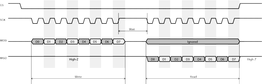
- In the communication protocol, the slave device always waits for the master to send fixed number of bytes (commands) from MOSI,
- then returns a fixed number of bytes to MISO.
- Some devices which transmit and receive data simultaneously cannot be used in half-duplex mode.
- The slave ignores whatever appears on the MOSI pin when transmitting data to the master.
- This is usually not mentioned in the datasheet.
- However, if the slave device mandates a CS or STROBE signal to be asserted at the beginning of each data exchange,
- we can usually assume this is true.
- Reason being that the slave device is using CS to reset its internal state
- rather than always listening and parsing command byte(s) from the master.
Half-duplex wiring of STM32 SPI is as follows:
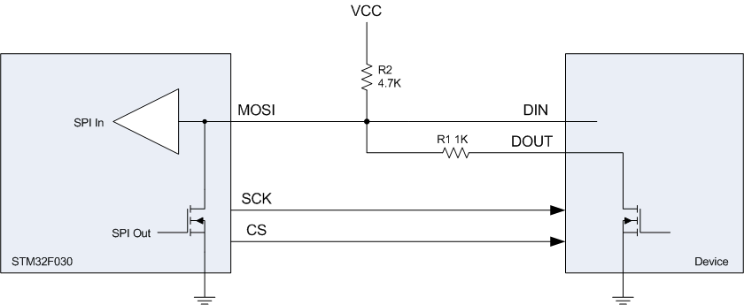
In particular, MOSI and SCK are configured as “Alternate Function” mode.
Hardware CS (NSS) management must be disabled and user shall manually control CS using GPIO output.
R2 is pull-up resistor as required by SPI.
R1 works as protection resistor in case STM32 MOSI pin somehow enters into push-pull output mode.
The SPI setup code is as follows:
void SPI_Configure()

{

    SPI_InitTypeDef SPI_InitStructure;

    // Enable SPI1 clock

    RCC_APB2PeriphClockCmd(RCC_APB2Periph_SPI1, ENABLE);

    // SPI1 configuration

    SPI_InitStructure.SPI_Direction = SPI_Direction_1Line_Tx; // Initially Tx

    SPI_InitStructure.SPI_Mode = SPI_Mode_Master;

    SPI_InitStructure.SPI_DataSize = SPI_DataSize_8b;

    SPI_InitStructure.SPI_CPOL = SPI_CPOL_High; // Clock steady high

    SPI_InitStructure.SPI_CPHA = SPI_CPHA_2Edge; // Data write on rising (second) edge

    SPI_InitStructure.SPI_NSS = SPI_NSS_Soft;

    SPI_InitStructure.SPI_BaudRatePrescaler = SPI_BaudRatePrescaler_64;

    SPI_InitStructure.SPI_FirstBit = SPI_FirstBit_LSB;

    SPI_InitStructure.SPI_CRCPolynomial = ;

    SPI_Init(SPI1, &SPI_InitStructure);

    SPI_RxFIFOThresholdConfig(SPI1, SPI_RxFIFOThreshold_QF);

    SPI_Cmd(SPI1, ENABLE);

}
Line 7 sets the SPI peripheral to half-dulex transmission mode.
Line 17 sets the SPI FIFO buffer threshold to quarter full.
This is new in STM32F0 with 4-byte SPI FIFO buffer.
SPI_RxFIFOThreshold_QF meaning that the SPI_I2S_FLAG_RXNE flag will be set as soon as 1 byte
(quarter buffer) is shifted into receiving FIFO.
SPI master sending data to slave is as simple as:
void send_byte(uint8_t val)

{

    GPIO_ResetBits(GPIOA, GPIO_Pin_4); // CS low

    while (SPI_I2S_GetFlagStatus(SPI1, SPI_I2S_FLAG_TXE) == RESET); //wait buffer empty

    SPI_SendData8(SPI1, val);

    while (SPI_I2S_GetFlagStatus(SPI1, SPI_I2S_FLAG_BSY) == SET); //wait finish sending

    GPIO_SetBits(GPIOA, GPIO_Pin_4); // CS high

}
The following code demonstrates master sends 1 byte command to slave and reads 1 byte back.
 uint8_t send_and_read_byte(uint8_t cmd)

 {

     uint8_t result;

     GPIO_ResetBits(GPIOA, GPIO_Pin_4); // CS low

     while (SPI_I2S_GetFlagStatus(SPI1, SPI_I2S_FLAG_TXE) == RESET); //wait buffer empty

     SPI_SendData8(SPI1, cmd);

     while (SPI_I2S_GetFlagStatus(SPI1, SPI_I2S_FLAG_BSY) == SET); //wait finish sending

     // Read receiving FIFO until it is empty

     while (SPI_GetReceptionFIFOStatus(SPI1) != SPI_ReceptionFIFOStatus_Empty)

         SPI_ReceiveData8(SPI1);

     SPI_BiDirectionalLineConfig(SPI1, SPI_Direction_Rx);

     while (!(SPI1->SR & SPI_I2S_FLAG_RXNE)) ; // wait data received

     GPIO_SetBits(GPIOA, GPIO_Pin_4); // CS high

     SPI1->CR1 |= SPI_Direction_Tx;  // Set Tx mode to stop Rx clock

     result = SPI_ReceiveData8(SPI1);

     return result;

 }
Immediately after one byte is sent, the program empties all stale data in the FIFO (line 9, 10),
then sets SPI direction to receiving mode (line 11).
As soon as SPI enters into receiving mode, STM32 will continuously generate clock on SCK pin until receiving mode is disabled.
Along with the clock toggling, data are shifted from MOSI pin into receiving FIFO,
and SPI_I2S_FLAG_RXNE flag is set once 1 byte of data is received (line 12).
The program then disables CS (line 13, to disable slave output)
and switches SPI back to transmitting mode (line 14, to stop the clock).
These two steps must be executed fast enough before the next clock is sent out to prevent the slave device enter into any undefined state.
Timing is very critical here especially when SPI clock is high.
To receive multiple bytes from the slave, put line 9-15 into a loop but disable CS only after all data are read.
Important thing is to always disable receiving mode immediately after FIFO is quarter full,
and verify using a scope or logic analyser to ensure exact 8 clocks are send in-between each reading.
HOWTO: Use STM32 SPI half duplex mode的更多相关文章
- The STM32 SPI and FPGA communication
The STM32 SPI and FPGA communication STM32 spi bus communication SPI bus in the study, the protocol ...
- 关于STM32 SPI NSS的讨论
NSS分为内部引脚和外部引脚. NSS外部引脚可以作为输入信号或者输出信号, 输入信号一般用作硬件方式从机的片选, 而输出信号一般用于主SPI去片选与之相连的从SPI. NSS从设备选择有两种模式: ...
- stm32 SPI介绍和配置
SPI是一种高速的,全双工同步的通信总线,在芯片管脚上占用了四根线,节约了芯片的管脚,同时为PCB的布局节省了空间,提供了方便,因此越来越多的芯片集成了这种通信协议,STM32也就有了SPI接口. 有 ...
- STM32 SPI 发送第一个数据不成功问题
STM32的标准库,跟HAL库都是很实用的, 在使用SPI库的过程中一定要注意时序的问题. 我在调试SPI过程中,调试了两个IC,都是用HAL库, 第一个IC没出问题,第二个IC出现了第一次发送数据不 ...
- STM32—SPI读写FLASH
目录 FLASH简介 W25Q64 W25Q64简介 FLASH控制指令 FLASH内部存储结构 代码讲解 读取芯片ID 发送写使能信号 等待FLASH不忙 擦除扇区 写入数据 读取数据 注 FLAS ...
- STM32—SPI详解
目录 一.什么是SPI 二.SPI协议 物理层 协议层 1.通讯时序图 2.起始和停止信号 3.数据有效性 4.通讯模式 三.STM32中的SPI 简介 功能框图 1.通讯引脚 2.时钟控制逻辑 3. ...
- STM32 SPI DMA 的使用
一是想总结一下SPI总线的特点与注意点,二是总结一下SPI DMA的使用 一.SPI信号线说明 通常SPI通过4个引脚与外部器件相连: MISO:主设备输入/从设备输出引脚.该引脚在从模式下发送数据, ...
- STM32.SPI(25Q16)
1.首先认识下W25Q16DVSIG, SOP8 SPI FLASH 16MBIT 2MB(4096个字节) (里面可以放字库,图片,也可以程序掉电不丢失数据放里面) 例程讲解: ① 1.用到SPI ...
- 2.2寸(14PIN)TFT液晶屏STM32 SPI 控制
屏幕如图所示,共14个IO口(也可能只有13个),控制屏幕的有9个IO口 详细版介绍见:http://www.ciast.net/post/20151112.html 反面IO口图: 连接通过SPI方 ...
随机推荐
- HDU 2521 反素数 模拟题
解题报告:水题,直接附上代码,只是觉得这题的作者是不是吃饱了饭撑的,反素数的概念跟这题一点关系都没有. #include<cstdio> int judge1(int k) { ; ;i& ...
- mysql学习------二进制日志管理
MySQL二进制日志(Binary Log) a.它包含的内容及作用如下: 包含了所有更新了数据或者已经潜在更新了数据(比如没有匹配任何行的一个DELETE) 包含关于每个更新数据库( ...
- Linux中断(interrupt)子系统之三:中断流控处理层【转】
转自:http://blog.csdn.net/droidphone/article/details/7489756 1. 中断流控层简介 早期的内核版本中,几乎所有的中断都是由__do_IRQ函数 ...
- appium-Could not obtain screenshot: [object Object]
原因 App页面已经被禁止截屏,禁用用户截屏的代码如下: getWindow().addFlags(WindowManager.LayoutParams.FLAG_SECURE); setConten ...
- cefsharp保存文件为pdf
var success = await browserViewModel.WebBrowser.PrintToPdfAsync(dialog.FileName, new PdfPrintSetting ...
- (mysql)触发器、事件、事务、函数
1.事务操作原理:事务开启之后Start transaction,所有的操作都会临时保存到事务日志.只有在得到commit才会关闭,否则清空:2.设置回滚点: savepoint 回滚点名字: 回到 ...
- vs2017 Remote Debugger远程调试目录
默认目录:C:\Program Files (x86)\Microsoft Visual Studio\2017\Community\Common7\IDE\Remote Debugger
- JavaScriptSerializer中日期序列化解决方案
后台代码: JavaScriptSerializer _jsSerializer = new JavaScriptSerializer(); ViewBag.ProcName = ProcInst.P ...
- 大数据统计分析平台之一、Kafka单机搭建
1.zookeeper搭建 Kafka集群依赖zookeeper,需要提前搭建好zookeeper 单机模式(7步)(集群模式进阶请移步:http://blog.51cto.com/nileader/ ...
- poj 1797 一条路径中的最小边 再找出最大的
Sample Input 1 // T3 3// n m1 2 3//u v w1 3 42 3 5Sample Output Scenario #1:4 # include <iostream ...