Cisco基础(六):配置目前网络环境、项目阶段练习
一、配置目前网络环境
目标:
一家新创建的IT公司,公司位于北京有80多台服务器
目前网络环境使用技术,通过端口映射技术将web服务器发布给Internet:
- 三层交换:汇聚接入层交换机
- 默认路由:实现到互联网数以万计网络访问的简化配置
- 静态路由:实现公司内部网络互通
- NAT端口映射:实现企业内部Web服务器的发布
方案:
通过端口映射技术将web服务器发布给Internet,公司现有网络环境拓扑如下图所示:
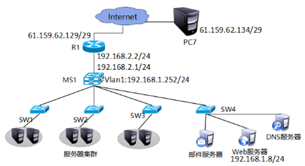
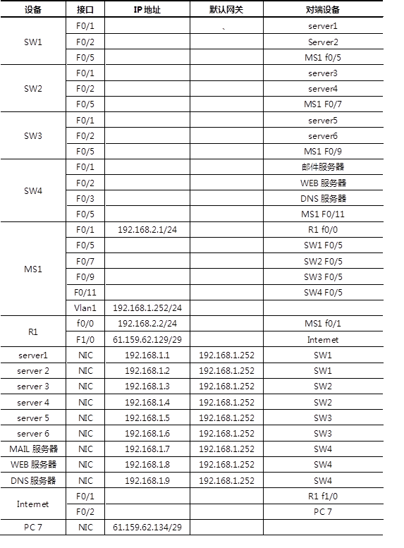
现有网络连接说明如下表所示:
步骤:
步骤一:根据表-1为设备配置IP地址,并为三层交换机开启路由功能
1)MS1配置vlan1与f0/1接口的IP地址并开启路由功能
Switch(config)#hostname MS1
MS1(config)#ip routing
MS1(config)#interface vlan 1
MS1(config-if)#ip address 192.168.1.252 255.255.255.0
MS1(config-if)#no shutdown
MS1(config-if)#exit
MS1(config-if)#interface fastEthernet 0/1
MS1(config-if)#no switchport
MS1(config-if)#ip address 192.168.2.1 255.255.255.0
MS1(config-if)#no shutdown
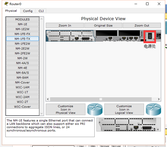
步骤二:为路由器配置IP地址,添加接口模块
1)为路由器添加接口模块并进入路由器接口配置IP地址
Router(config)#hostname R1
R1(config)#interface fastEthernet 0/0
R1(config-if)#ip address 192.168.2.2 255.255.255.0
R1(config-if)#no shutdown
R1(config-if)#exit
R1(config)#interface fastEthernet 1/0
R1(config-if)#ip address 61.159.62.129 255.255.255.248
R1(config-if)#no shutdown
步骤三:配置MS1和路由器的静态路由
MS1(config-if)#ip route 0.0.0.0 0.0.0.0 192.168.2.2
R1(config)#ip route 192.168.1.0 255.255.255.0 192.168.2.1
步骤四:测试server1与R1接口IP的连通性
PC>ping 192.168.2.2
Pinging 192.168.2.2 with 32 bytes of data:
Reply from 192.168.2.2: bytes=32 time=0ms TTL=254
Reply from 192.168.2.2: bytes=32 time=0ms TTL=254
Reply from 192.168.2.2: bytes=32 time=0ms TTL=254
Reply from 192.168.2.2: bytes=32 time=1ms TTL=254
Ping statistics for 192.168.2.2:
Packets: Sent = 4, Received = 4, Lost = 0 (0% loss),
Approximate round trip times in milli-seconds:
Minimum = 0ms, Maximum = 1ms, Average = 0ms
PC>ping 61.159.62.129
Pinging 61.159.62.129 with 32 bytes of data:
Reply from 61.159.62.129: bytes=32 time=1ms TTL=254
Reply from 61.159.62.129: bytes=32 time=0ms TTL=254
Reply from 61.159.62.129: bytes=32 time=2ms TTL=254
Reply from 61.159.62.129: bytes=32 time=0ms TTL=254
Ping statistics for 61.159.62.129:
Packets: Sent = 4, Received = 4, Lost = 0 (0% loss),
Approximate round trip times in milli-seconds:
Minimum = 0ms, Maximum = 2ms, Average = 0ms
步骤五:R1配置端口映射
R1(config)#ip nat inside source static tcp 192.168.1.8 80 61.159.62.131 80
R1(config)#interface fastEthernet 0/0
R1(config-if)#ip nat inside
R1(config)#interface f1/0
R1(config-if)#ip nat outside
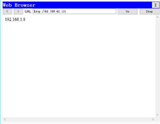
步骤六:在PC7上查看是映射结果,如下图所示

二、项目阶段练习
目标:
现有网络问题分析:
- 接入层交换机只与同一个三层交换机相连,存在单点故障而影响网络通信。
- 互联网连接单一服务商
现有网络需求:
- 随着企业发展,为了保证网络的高可用性,需要使用很多的冗余技术。
- 保证局域网络不会因为线路故障而导致的网络故障。
- 保证客户端机器不会因为使用单一网关而出现的单点失败。
- 保证到互联网的高可用接入使用冗余互联网连接。
- 提高网络链路带宽。
方案:
基于项目的需求,需要用到如下技术:
- STP:解决二层环路带来的广播风暴并链路冗余问题
- 以太网通道:提高网络链路带宽
- RIP路由协议:实现网络路径的自动学习
- HSRP:实现网关冗余
重新规划后的网络拓扑如下图:
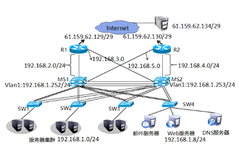
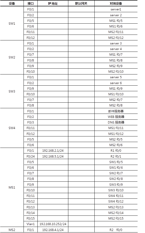
重新规划后网络连接说明如下表所示:

步骤:
步骤一:静态路由升级动态路由。
1)R1删除静态路由并配置rip
R1(config)#no ip route 192.168.1.0 255.255.255.0 192.168.2.1
R1(config)#router rip
R1(config-router)#version 2
R1(config-router)#no auto-summary
R1(config-router)#network 192.168.2.0
R1(config-router)#default-information originate
2)MS1上删除静态路由并配置rip
MS1(config)#no ip route 0.0.0.0 0.0.0.0 192.168.2.2
MS1(config)#router rip
MS1(config-router)#version 2
MS1(config-router)#no auto-summary
MS1(config-router)#network 192.168.1.0
MS1(config-router)#network 192.168.2.0
3)在MS1上查看路由表
MS1#show ip route
Codes: C - connected, S - static, I - IGRP, R - RIP, M - mobile, B - BGP
D - EIGRP, EX - EIGRP external, O - OSPF, IA - OSPF inter area
N1 - OSPF NSSA external type 1, N2 - OSPF NSSA external type 2
E1 - OSPF external type 1, E2 - OSPF external type 2, E - EGP
i - IS-IS, L1 - IS-IS level-1, L2 - IS-IS level-2, ia - IS-IS inter area
* - candidate default, U - per-user static route, o - ODR
P - periodic downloaded static route
Gateway of last resort is 192.168.2.2 to network 0.0.0.0
C 192.168.1.0/24 is directly connected, Vlan1
C 192.168.2.0/24 is directly connected, FastEthernet0/1
R* 0.0.0.0/0 [120/1] via 192.168.2.2, 00:00:01, FastEthernet0/1
步骤二:配置SW1、SW2、SW3、SW4与MS1的接口为Trunk模式并做以太网通道。
1)SW1、SW2、SW3、SW4上做与MS1之间的trunk与以太网通道
Switch(config)#hostname SW1
SW1(config)#interface range fastEthernet 0/5-6
SW1(config-if-range)#switchport mode trunk
SW1(config-if-range)#channel-group 1 mode on
Switch(config)#hostname SW2
SW2(config)#interface range fastEthernet 0/7-8
SW2(config-if-range)#switchport mode trunk
SW2(config-if-range)#channel-group 2 mode on
Switch(config)#hostname SW3
SW3(config)#interface range fastEthernet 0/9-10
SW3(config-if-range)#switchport mode trunk
SW3(config-if-range)#channel-group 3 mode on
Switch(config)#hostname SW4
SW4(config)#interface range fastEthernet 0/11-12
SW4(config-if-range)#switchport mode trunk
SW4(config-if-range)#channel-group 4 mode on
2)MS1与SW1、SW2、SW3、SW4之间做以太网通道并启用trunk
MS1(config)#interface range fastEthernet 0/5-6
MS1(config-if-range)#switchport trunk encapsulation dot1q
MS1(config-if-range)#switchport mode trunk
MS1(config-if-range)#channel-group 1 mode on
MS1(config-if-range)#exit
MS1(config-if-range)#interface range fastEthernet 0/7-8
MS1(config-if-range)#switchport trunk encapsulation dot1q
MS1(config-if-range)#channel-group 2 mode on
MS1(config-if-range)#switchport mode trunk
MS1(config-if-range)#exit
MS1(config-if-range)#interface range fastEthernet 0/9-10
MS1(config-if-range)#switchport trunk encapsulation dot1q
MS1(config-if-range)#switchport mode trunk
MS1(config-if-range)#channel-group 3 mode on
MS1(config-if-range)#exit
MS1(config-if-range)#interface range fastEthernet 0/11-12
MS1(config-if-range)#switchport trunk encapsulation dot1q
MS1(config-if-range)#switchport mode trunk on
MS1(config-if-range)#channel-group 4 mode on
步骤三:添加MS2并配置与MS1、SW1、SW2、SW3、SW4之间的太网通道。
1)在MS1上配置与MS2的以太网通道
MS1(config)#interface range fastEthernet 0/13-15
MS1(config-if-range)#channel-group 5 mode on
MS1(config-if-range)#switchport trunk encapsulation dot1q
MS1(config-if-range)#switchport mode trunk
2)在MS2并配置与MS1、SW1、SW2、SW3、SW4之间的太网通道
MS2(config)#interface range fastEthernet 0/10-12
MS2(config-if-range)#channel-group 5 mode on
MS2(config-if-range)#switchport trunk encapsulation dot1q
MS2(config-if-range)#switchport mode trunk
MS2(config-if-range)#exit
MS2(config)#interface range fastEthernet 0/2-3
MS2(config-if-range)#channel-group 1 mode on
MS2(config-if-range)#switchport trunk encapsulation dot1q
MS2(config-if-range)#switchport mode trunk
MS2(config-if-range)#exit
MS2(config)#interface range fastEthernet 0/4-5
MS2(config-if-range)#channel-group 2 mode on
MS2(config-if-range)#switchport mode trunk
MS2(config-if-range)#exit
MS2(config)#interface range fastEthernet 0/6-7
MS2(config-if-range)#channel-group 3 mode on
MS2(config-if-range)#switchport trunk encapsulation dot1q
MS2(config-if-range)#switchport mode trunk
MS2(config-if-range)#exit
MS2(config)#interface range fastEthernet 0/8-9
MS2(config-if-range)#channel-group 4 mode on
MS2(config-if-range)#switchport trunk encapsulation dot1q
MS2(config-if-range)#switchport mode trunk
3)在MS1上查看以太网通道
MS1>show etherchannel port-channel
Channel-group listing:
----------------------
Group: 1
----------
Port-channels in the group:
---------------------------
Port-channel: Po1
------------
Age of the Port-channel = 00d:00h:05m:21s
Logical slot/port = 2/1 Number of ports = 2
GC = 0x00000000 HotStandBy port = null
Port state = Port-channel
Protocol = PAGP
Port Security = Disabled
Ports in the Port-channel:
Index Load Port EC state No of bits
------+------+------+------------------+-----------
0 00 Fa0/5 On 0
0 00 Fa0/6 On 0
Time since last port bundled: 00d:00h:05m:21s Fa0/6
Group: 2
----------
Port-channels in the group:
---------------------------
Port-channel: Po2
------------
Age of the Port-channel = 00d:00h:05m:21s
Logical slot/port = 2/2 Number of ports = 2
GC = 0x00000000 HotStandBy port = null
Port state = Port-channel
Protocol = PAGP
Port Security = Disabled
Ports in the Port-channel:
Index Load Port EC state No of bits
------+------+------+------------------+-----------
0 00 Fa0/7 On 0
0 00 Fa0/8 On 0
Time since last port bundled: 00d:00h:05m:21s Fa0/8
Group: 3
----------
Port-channels in the group:
---------------------------
Port-channel: Po3
------------
Age of the Port-channel = 00d:00h:05m:21s
Logical slot/port = 2/3 Number of ports = 2
GC = 0x00000000 HotStandBy port = null
Port state = Port-channel
Protocol = PAGP
Port Security = Disabled
Ports in the Port-channel:
Index Load Port EC state No of bits
------+------+------+------------------+-----------
0 00 Fa0/9 On 0
0 00 Fa0/10 On 0
Time since last port bundled: 00d:00h:05m:21s Fa0/10
Group: 4
----------
Port-channels in the group:
---------------------------
Port-channel: Po4
------------
Age of the Port-channel = 00d:00h:05m:21s
Logical slot/port = 2/4 Number of ports = 2
GC = 0x00000000 HotStandBy port = null
Port state = Port-channel
Protocol = PAGP
Port Security = Disabled
Ports in the Port-channel:
Index Load Port EC state No of bits
------+------+------+------------------+-----------
0 00 Fa0/11 On 0
0 00 Fa0/12 On 0
Time since last port bundled: 00d:00h:05m:21s Fa0/12
Group: 5
----------
Port-channels in the group:
---------------------------
Port-channel: Po5
------------
Age of the Port-channel = 00d:00h:08m:11s
Logical slot/port = 2/5 Number of ports = 3
GC = 0x00000000 HotStandBy port = null
Port state = Port-channel
Protocol = PAGP
Port Security = Disabled
Ports in the Port-channel:
Index Load Port EC state No of bits
------+------+------+------------------+-----------
0 00 Fa0/13 On 0
0 00 Fa0/14 On 0
0 00 Fa0/15 On 0
Time since last port bundled: 00d:00h:08m:11s Fa0/15
步骤四:MS1与MS2配置STP
1)在MS1和MS2上配置stp
MS1(config)#spanning-tree vlan 1 root primary
MS2(config)#spanning-tree vlan 1 root secondary
2)在MS1和MS2上查看stp
MS1# show spanning-tree vlan 1
VLAN0001
Spanning tree enabled protocol ieee
Root ID Priority 24577
Address 0004.9A70.6B06
This bridge is the root
Hello Time 2 sec Max Age 20 sec Forward Delay 15 sec
Bridge ID Priority 24577 (priority 24576 sys-id-ext 1)
Address 0004.9A70.6B06
Hello Time 2 sec Max Age 20 sec Forward Delay 15 sec
Aging Time 20
Interface Role Sts Cost Prio.Nbr Type
---------------- ---- --- --------- -------- --------------------------------
Po1 Desg FWD 9 128.27 Shr
Po2 Desg FWD 9 128.28 Shr
Po3 Desg FWD 9 128.29 Shr
Po4 Desg FWD 9 128.30 Shr
Po5 Desg FWD 8 128.31 Shr
MS2#show spanning-tree vlan 1
VLAN0001
Spanning tree enabled protocol ieee
Root ID Priority 24577
Address 0004.9A70.6B06
Cost 8
Port 31(Port-channel 5)
Hello Time 2 sec Max Age 20 sec Forward Delay 15 sec
Bridge ID Priority 28673 (priority 28672 sys-id-ext 1)
Address 0006.2A05.A2BA
Hello Time 2 sec Max Age 20 sec Forward Delay 15 sec
Aging Time 20
Interface Role Sts Cost Prio.Nbr Type
---------------- ---- --- --------- -------- --------------------------------
Po1 Desg FWD 9 128.27 Shr
Po2 Desg FWD 9 128.28 Shr
Po3 Desg FWD 9 128.29 Shr
Po4 Desg FWD 9 128.30 Shr
Po5 Root FWD 8 128.31 Shr
步骤五:HSRP配置
1)MS1配置HSRP
MS1(config)#interface vlan 1
MS1(config-if)#standby 1 ip 192.168.1.254
MS1(config-if)#standby 1 priority 200
MS1(config-if)#standby 1 preempt
2)MS2配置HSRP开启路由功能
MS2(config)#ip routing
MS2(config)#interface vlan 1
MS2(config)#ip address 192.168.1.253 255.255.255.0
MS2(config)#no shutdown
MS2(config-if)#standby 1 ip 192.168.1.254
MS2(config-if)#standby 1 priority 195
MS2(config-if)#standby 1 preempt
3)配置MS1交换机的HSRP的端口跟踪,关闭跟踪接口,并在MS1和MS2上查看HSRP状态
MS1(config)# MS1(config)#interface vlan 1
MS1(config-if)#standby 1 track fastEthernet 0/1
MS1(config-if)#exit
MS1(config)#interface fastEthernet 0/1
MS1(config-if)#shutdown
MS1#show standby brief
P indicates configured to preempt.
|
Interface Grp Pri P State Active Standby Virtual IP
Vl1 1 190 P Standby 192.168.1.253 local 192.168.1.254
MS2#show standby brief
P indicates configured to preempt.
Interface Grp Pri P State Active Standby Virtual IP
Vl1 1 195 P Active local 192.168.1.252 192.168.1.254
步骤六:MS2连接R1并配置rip
1)为R1与MS2相连接的接口配置IP地址 并配置rip
R1(config)#interface fastEthernet 0/24
R1(config-if)#ip address 192.168.3.2 255.255.255.0
R1(config-if)#exit
R1(config)#router rip
R1(config-router)# version 2
R1(config-router)#network 192.168.3.0
MS2(config-if)#exit
MS2(config)#router rip
MS2(config-router)#version 2
MS2(config-router)#no auto-summary
MS2(config-router)#network 192.168.1.0
步骤七:添加路由器R2, 为R2配置默认路由,R2与MS1、MS2、Internet相连并为配置IP与动态路由
1)配置R2的IP地址、rip、默认路由。
Router(config)hostname R2
R2(config)#interface fastEthernet 0/0
R2(config-if)#ip address 192.168.4.2 255.255.255.0
R2(config-if)#no shutdown
R2(config-if)#exit
R2(config)#interface fastEthernet 0/1
R2(config-if)#ip address 192.168.5.2 255.255.255.0
R2(config-if)#no shutdown
R2(config-if)#exit
R2(config)#interface fastEthernet 1/0
R2(config-if)#ip address 61.159.62.130 255.255.255.248
R2(config-if)#no shutdown
R2(config-if)#exit
R2(config)ip route 0.0.0.0 0.0.0.0 fastEthernet 1/0
R2(config)#router rip
R2(config-router)#version 2
R2(config-router)#no auto-summary
R2(config-router)#network 192.168.4.0
R2(config-router)#network 192.168.5.0
R2(config-router)#default-information originate
2)MS2配置IP地址添加动态路由条目
MS2(config)#interface fastEthernet 0/1
MS2(config-if)#no switchport
MS2(config-if)#ip address 192.168.4.1 255.255.255.0
MS2(config-if)#no shutdown
MS2(config-if)#exit
MS2(config)#router rip
R2(config-router)#version 2
MS2(config-router)#network 192.168.4.0
3)MS1配置IP地址添加动态路由条目
MS1(config)#interface fastEthernet 0/24
MS1(config-if)#no switchport
MS1(config-if)#ip address 192.168.5.1 255.255.255.0
MS1(config-if)#no shutdown
MS1(config-if)#exit
MS1(config)#router rip
R2(config-router)#version 2
MS1(config-router)#network 192.168.5.0
4)在客户端测试网络的联通性
SERVER>ipconfig
FastEthernet0 Connection:(default port)
Link-local IPv6 Address.........: FE80::201:96FF:FEA8:404B
IP Address......................: 192.168.1.1
Subnet Mask.....................: 255.255.255.0
Default Gateway.................: 192.168.1.254
SERVER>ping 192.168.2.1
Pinging 192.168.2.1 with 32 bytes of data:
Reply from 192.168.2.1: bytes=32 time=0ms TTL=255
Reply from 192.168.2.1: bytes=32 time=0ms TTL=255
Reply from 192.168.2.1: bytes=32 time=0ms TTL=255
Reply from 192.168.2.1: bytes=32 time=0ms TTL=255
Ping statistics for 192.168.2.1:
Packets: Sent = 4, Received = 4, Lost = 0 (0% loss),
Approximate round trip times in milli-seconds:
Minimum = 0ms, Maximum = 0ms, Average = 0ms
SERVER>ping 192.168.3.1
Pinging 192.168.3.1 with 32 bytes of data:
Reply from 192.168.3.1: bytes=32 time=0ms TTL=255
Reply from 192.168.3.1: bytes=32 time=0ms TTL=255
Reply from 192.168.3.1: bytes=32 time=0ms TTL=255
Reply from 192.168.3.1: bytes=32 time=0ms TTL=255
Ping statistics for 192.168.3.1:
Packets: Sent = 4, Received = 2, Lost = 2 (50% loss),
Approximate round trip times in milli-seconds:
Minimum = 0ms, Maximum = 0ms, Average = 0ms
SERVER>ping 192.168.4.1
Pinging 192.168.4.1 with 32 bytes of data:
Reply from 192.168.4.1: bytes=32 time=1ms TTL=255
Reply from 192.168.4.1: bytes=32 time=0ms TTL=255
Reply from 192.168.4.1: bytes=32 time=0ms TTL=255
Reply from 192.168.4.1: bytes=32 time=0ms TTL=255
Ping statistics for 192.168.4.1:
Packets: Sent = 4, Received = 4, Lost = 0 (0% loss),
Approximate round trip times in milli-seconds:
Minimum = 0ms, Maximum = 1ms, Average = 0ms
SERVER>ping 192.168.5.1
Pinging 192.168.5.1 with 32 bytes of data:
Reply from 192.168.5.1: bytes=32 time=1ms TTL=255
Reply from 192.168.5.1: bytes=32 time=1ms TTL=255
Reply from 192.168.5.1: bytes=32 time=1ms TTL=255
Reply from 192.168.5.1: bytes=32 time=0ms TTL=255
Ping statistics for 192.168.5.1:
Packets: Sent = 4, Received = 4, Lost = 0 (0% loss),
Approximate round trip times in milli-seconds:
Minimum = 0ms, Maximum = 1ms, Average = 0ms
SERVER>ping 192.168.2.2
Pinging 192.168.2.2 with 32 bytes of data:
Reply from 192.168.2.2: bytes=32 time=1ms TTL=254
Reply from 192.168.2.2: bytes=32 time=1ms TTL=254
Reply from 192.168.2.2: bytes=32 time=11ms TTL=254
Reply from 192.168.2.2: bytes=32 time=0ms TTL=254
Ping statistics for 192.168.2.2:
Packets: Sent = 4, Received = 4, Lost = 0 (0% loss),
Approximate round trip times in milli-seconds:
Minimum = 0ms, Maximum = 11ms, Average = 3ms
SERVER>ping 192.168.3.2
Pinging 192.168.3.2 with 32 bytes of data:
Reply from 192.168.3.2: bytes=32 time=0ms TTL=254
Reply from 192.168.3.2: bytes=32 time=0ms TTL=254
Reply from 192.168.3.2: bytes=32 time=1ms TTL=254
Reply from 192.168.3.2: bytes=32 time=0ms TTL=254
Ping statistics for 192.168.3.2:
Packets: Sent = 4, Received = 4, Lost = 0 (0% loss),
Approximate round trip times in milli-seconds:
Minimum = 0ms, Maximum = 1ms, Average = 0ms
5)关闭MS1
MS1(config)#interface range fastEthernet 0/1-24
MS1(config-if-range)#shutdown
6)在外网测试是否可以访问web服务器如下图所示
步骤八:在R2上配置端口映射
1)在R2上配置端口映射,指定NAT进口
R2(config)#ip nat inside source static tcp 192.168.1.8 80 61.159.62.131 80
R2(config)#interface fastEthernet 0/0
R2(config-if)#ip nat inside
R2(config-if)#exit
R2(config)#interface fastEthernet 0/1
R2(config-if)#ip nat inside
R2(config-if)#exit
R2(config)#interface fastEthernet 1/0
R2(config-if)#ip nat outside
2)关闭R1(如下图所示)测试外网是否可以正常访问web服务器(因为模拟器有BUG所以需要填加一台Internet主机IP:61.159.62.133测试如下下图所示)
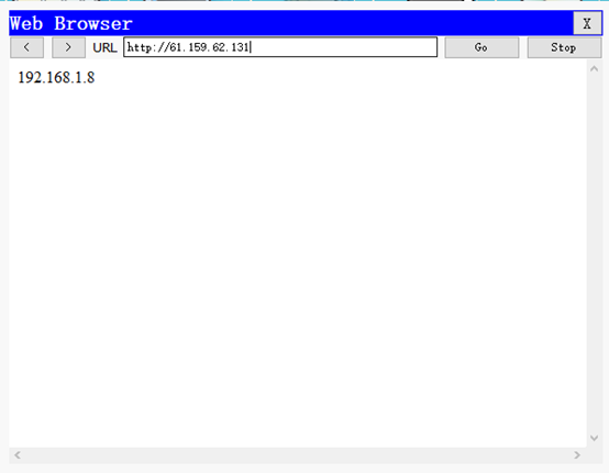
可以访问web服务器证明项目升级成功。
Cisco基础(六):配置目前网络环境、项目阶段练习的更多相关文章
- OCM_第二天课程:Section1 —》配置 Oracle 网络环境
注:本文为原著(其内容来自 腾科教育培训课堂).阅读本文注意事项如下: 1:所有文章的转载请标注本文出处. 2:本文非本人不得用于商业用途.违者将承当相应法律责任. 3:该系列文章目录列表: 一:&l ...
- OCA读书笔记(6) - 配置Oracle网络环境
6.Configuring the Oracle Network Environment su - grid装grid时自动创建了监听netca--创建新的监听 vi $ORACLE_HOME/net ...
- linux配置虚拟机网络环境(老师要求的host-only)
我这个人就是懒,这TMD是全天下最坑爹的缺点了,当然爆粗口也是缺点,让我发泄一下吧.T^T 从n久之前,开了hadoop课的一天,我就想着要配置好,结果两次课连眼镜都忘了带,可想而知是什么陪我度过了那 ...
- Linux初识之VMWare14中配置Centos7桥接网络环境
1.查看当前初始环境如下:
- Linux的VMWare14中配置Centos7桥接网络环境(网络一)
1.查看当前初始环境如下:在windows端先查看本机ip ifconfig
- Redhat6.4 配置本地网络的FTP YUM源
Redhat6.4 配置本地网络的FTP YUM源 如果本机IP: 192.168.8.47 (一) 配置本机的yum源 使用以下的方法能够配置本机的yum源: 1) scp命令上传ISO文件到: / ...
- CentOs7 最小安装版安装后配置和java环境的搭建
下面是contos7 最小化安装成功以后进行一些基础的配置和java环境的安装教程: 1 防火墙 : 关闭防火墙: systemctl stop firewalld.service . 关闭开机启 ...
- VirtualBox虚拟机网络环境Host-Only(对Win10和VirtualBox都有截图)
之前在选择配置虚拟机网络环境的时候 桥接也是不错的,但是自己在使用的时候由于访问频繁会出现断网现象.所以就开始使用Host-Only模式.开始并不是很明白为什么这么设置,也挖了很多坑.经常出现虚拟机无 ...
- CentOS(六)--Linux系统的网络环境配置
Linux系统下的网络环境配置,Linux.Unix就是网络的世界,所以在Linux系统中如何配置网络环境变量是至关重要的,这里将会给出3种Linux系统下网络环境配置的方法! 在配置网络环境之前,首 ...
随机推荐
- fedora下编译运行java傻瓜入门级教程
操作步骤: 编译运行环境的搭建 fedora下默认安装为GNU公司的JDK,如下所示 $java -version java version "1.7.0_25" OpenJDK ...
- Python基础教程(018)--官方解释器交互运行
前言: 在交互式运行Python程序 内容 在Python的shell中直接输入Python的代码,可以立即执行结果 交互式运行Python的优缺点 1,缺点--代码不能保存 2,不适合运行太大的程序 ...
- 10.15 sed 命令实践
在n行前插入 [root@wen data]# sed '2i 106,dandan,CSO' person.txt101,oldboy,CEO106,dandan,CSO102,zhangyao,C ...
- AGC013 E Placing Squares——模型转化+矩阵乘法
题目:https://atcoder.jp/contests/agc013/tasks/agc013_e 边长的平方,可以看做是在该范围内放两个不同的球的方案数.两个球可以重合. 题意变成:给长为 n ...
- HTTP的FormData和Payload的传输格式
FormData和Payload是浏览器传输给接口的两种格式,这两种方式浏览器是通过Content-Type来进行区分的(了解Content-Type),如果是 application/x-www-f ...
- Infinity、-Infinity和NaN
首先看看这三个代表什么: Infinity:正无穷大 -Infinity:负无穷大 NaN:Not a Number 当float或double类型的数除零时, 当被除数为非零值时,结果为无穷大 当被 ...
- QTP使用dictionary 对象
1. 创建即使用Dictionary对象 ' 创建Dictionary对象Set Dic = CreateObject("Scripting.Dictionary")' 添加Dic ...
- SpringMVC上传文件的三种方式(转帖)
/* * 通过流的方式上传文件 * @RequestParam("file") 将name=file控件得到的文件封装成CommonsMultipartFile 对象 */ @Re ...
- 洛谷 P1197 [JSOI2008]星球大战——并查集
先上一波题目 https://www.luogu.org/problem/P1197 很明显删除的操作并不好处理 那么我们可以考虑把删边变成加边 只需要一波时间倒流就可以解决拉 储存删边顺序倒过来加边 ...
- 为GitLab帐号添加SSH keys并连接GitLab
https://blog.csdn.net/xyzchenxiaolin/article/details/51852333 为github帐号添加SSH keys使用git clone命令从GitLa ...