STM32F4 External interrupts
STM32F4 External interrupts
Each STM32F4 device has 23 external interrupt or event sources.
They are split into 2 sections.
First interrupt section is for external pins (P0 to P15) on each port,
and other section is for other events, like RTC interrupt, Ethernet interrupt, USB interrupt and so on.

GPIO as Interrupt
Interrupt lines
I will show now how to configure GPIO pin to be an interrupt and how to handle it in your code with CMSIS function.
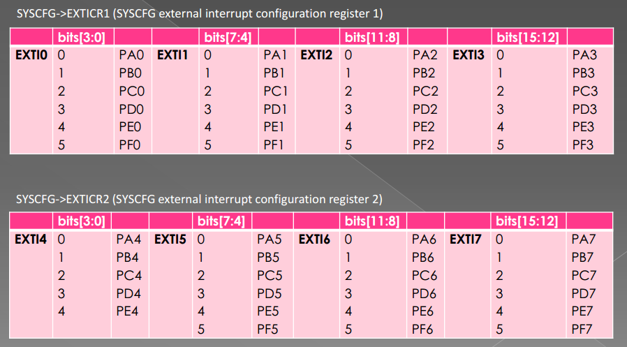
In section one (GPIOs) we have 16 interrupt lines.
They are line0 to line15 and they also represent pin number.
This means, PA0 is connected to Line0and PA13 is connected to Line13.
You have to know that PB0 is also connected to Line0 and PC0 also and so on.
This is for all pins on board, All Px0 (where x is GPIO name) pins are connected to Line0
and let’s say all Px3 are connected to Line3 on the Interrupt channel.
All pins with same number are connected to line with same number.
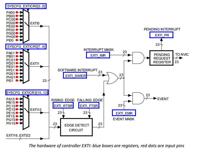
They are multiplexed to one line.
IMPORTANT: You can not use two pins on one line simultaneously:
- PA0 and PB0 and PC0 and so on, are connected to Line0,
so you can use only one pin at one time to handle interrupt from there. - PA0 and PA5 are connected to different lines, they can be used at the same time.
Each line can trigger an interrupt on rising, falling or rising_falling enge on signal.
Interrupt handlers
OK, now you have selected your pin you want to use.
But you have to handle interrupt somehow.
This process is described below.
STM32F4 has 7 interrupt handlers for GPIO pins.
They are in table below:
| Irq | Handler | Description |
|---|---|---|
| EXTI0_IRQn | EXTI0_IRQHandler | Handler for pins connected to line 0 |
| EXTI1_IRQn | EXTI1_IRQHandler | Handler for pins connected to line 1 |
| EXTI2_IRQn | EXTI2_IRQHandler | Handler for pins connected to line 2 |
| EXTI3_IRQn | EXTI3_IRQHandler | Handler for pins connected to line 3 |
| EXTI4_IRQn | EXTI4_IRQHandler | Handler for pins connected to line 4 |
| EXTI9_5_IRQn | EXTI9_5_IRQHandler | Handler for pins connected to line 5 to 9 |
| EXTI15_10_IRQn | EXTI15_10_IRQHandler | Handler for pins connected to line 10 to 15 |
This table show you which IRQ you have to set for NVIC (first column)
and function names to handle your interrupts (second column).
You have probably also figured, that only lines 0 to 4 have own IRQ handler.
Yes, lines 5-9 have the same interrupt handler and this is also for lines 10 to 15.
After you set settings for EXTI, you have to add them into NVIC.
Example
In this example, we will set pin PD0 and PB12 to be a GPIO interrupts.
Code below should be well documented to understand how it works.
/**

 *    External interrupts example

 *

 *    @author     Tilen Majerle

 *    @email        tilen@majerle.eu

 *    @website    http://stm32f4-discovery.com

 *    @ide        Keil uVision 5

 */

#include "stm32f4xx.h"

#include "stm32f4xx_exti.h"

#include "stm32f4xx_syscfg.h"

#include "misc.h"

/* Configure pins to be interrupts */

void Configure_PD0(void) {

    /* Set variables used */

    GPIO_InitTypeDef GPIO_InitStruct;

    EXTI_InitTypeDef EXTI_InitStruct;

    NVIC_InitTypeDef NVIC_InitStruct;

    /* Enable clock for GPIOD */

    RCC_AHB1PeriphClockCmd(RCC_AHB1Periph_GPIOD, ENABLE);

    /* Enable clock for SYSCFG */

    RCC_APB2PeriphClockCmd(RCC_APB2Periph_SYSCFG, ENABLE);

    /* Set pin as input */

    GPIO_InitStruct.GPIO_Mode = GPIO_Mode_IN;

    GPIO_InitStruct.GPIO_OType = GPIO_OType_PP;

    GPIO_InitStruct.GPIO_Pin = GPIO_Pin_0;

    GPIO_InitStruct.GPIO_PuPd = GPIO_PuPd_UP;

    GPIO_InitStruct.GPIO_Speed = GPIO_Speed_100MHz;

    GPIO_Init(GPIOD, &GPIO_InitStruct);

    /* Tell system that you will use PD0 for EXTI_Line0 */

    SYSCFG_EXTILineConfig(EXTI_PortSourceGPIOD, EXTI_PinSource0);

    /* PD0 is connected to EXTI_Line0 */

    EXTI_InitStruct.EXTI_Line = EXTI_Line0;

    /* Enable interrupt */

    EXTI_InitStruct.EXTI_LineCmd = ENABLE;

    /* Interrupt mode */

    EXTI_InitStruct.EXTI_Mode = EXTI_Mode_Interrupt;

    /* Triggers on rising and falling edge */

    EXTI_InitStruct.EXTI_Trigger = EXTI_Trigger_Rising_Falling;

    /* Add to EXTI */

    EXTI_Init(&EXTI_InitStruct);

    /* Add IRQ vector to NVIC */

    /* PD0 is connected to EXTI_Line0, which has EXTI0_IRQn vector */

    NVIC_InitStruct.NVIC_IRQChannel = EXTI0_IRQn;

    /* Set priority */

    NVIC_InitStruct.NVIC_IRQChannelPreemptionPriority = 0x00;

    /* Set sub priority */

    NVIC_InitStruct.NVIC_IRQChannelSubPriority = 0x00;

    /* Enable interrupt */

    NVIC_InitStruct.NVIC_IRQChannelCmd = ENABLE;

    /* Add to NVIC */

    NVIC_Init(&NVIC_InitStruct);

}

void Configure_PB12(void) {

    /* Set variables used */

    GPIO_InitTypeDef GPIO_InitStruct;

    EXTI_InitTypeDef EXTI_InitStruct;

    NVIC_InitTypeDef NVIC_InitStruct;

    /* Enable clock for GPIOB */

    RCC_AHB1PeriphClockCmd(RCC_AHB1Periph_GPIOB, ENABLE);

    /* Enable clock for SYSCFG */

    RCC_APB2PeriphClockCmd(RCC_APB2Periph_SYSCFG, ENABLE);

    /* Set pin as input */

    GPIO_InitStruct.GPIO_Mode = GPIO_Mode_IN;

    GPIO_InitStruct.GPIO_OType = GPIO_OType_PP;

    GPIO_InitStruct.GPIO_Pin = GPIO_Pin_12;

    GPIO_InitStruct.GPIO_PuPd = GPIO_PuPd_UP;

    GPIO_InitStruct.GPIO_Speed = GPIO_Speed_100MHz;

    GPIO_Init(GPIOB, &GPIO_InitStruct);

    /* Tell system that you will use PB12 for EXTI_Line12 */

    SYSCFG_EXTILineConfig(EXTI_PortSourceGPIOB, EXTI_PinSource12);

    /* PB12 is connected to EXTI_Line12 */

    EXTI_InitStruct.EXTI_Line = EXTI_Line12;

    /* Enable interrupt */

    EXTI_InitStruct.EXTI_LineCmd = ENABLE;

    /* Interrupt mode */

    EXTI_InitStruct.EXTI_Mode = EXTI_Mode_Interrupt;

    /* Triggers on rising and falling edge */

    EXTI_InitStruct.EXTI_Trigger = EXTI_Trigger_Rising_Falling;

    /* Add to EXTI */

    EXTI_Init(&EXTI_InitStruct);

    /* Add IRQ vector to NVIC */

    /* PB12 is connected to EXTI_Line12, which has EXTI15_10_IRQn vector */

    NVIC_InitStruct.NVIC_IRQChannel = EXTI15_10_IRQn;

    /* Set priority */

    NVIC_InitStruct.NVIC_IRQChannelPreemptionPriority = 0x00;

    /* Set sub priority */

    NVIC_InitStruct.NVIC_IRQChannelSubPriority = 0x01;

    /* Enable interrupt */

    NVIC_InitStruct.NVIC_IRQChannelCmd = ENABLE;

    /* Add to NVIC */

    NVIC_Init(&NVIC_InitStruct);

}

/* Set interrupt handlers */

/* Handle PD0 interrupt */

void EXTI0_IRQHandler(void) {

    /* Make sure that interrupt flag is set */

    if (EXTI_GetITStatus(EXTI_Line0) != RESET) {

        /* Do your stuff when PD0 is changed */

        /* Clear interrupt flag */

        EXTI_ClearITPendingBit(EXTI_Line0);

    }

}

/* Handle PB12 interrupt */

void EXTI15_10_IRQHandler(void) {

    /* Make sure that interrupt flag is set */

    if (EXTI_GetITStatus(EXTI_Line12) != RESET) {

        /* Do your stuff when PB12 is changed */

        /* Clear interrupt flag */

        EXTI_ClearITPendingBit(EXTI_Line12);

    }

}

int main(void) {

    /* System init */

    SystemInit();

    /* Configure PD0 as interrupt */

    Configure_PD0();

    /* Configure PB12 as interrupt */

    Configure_PB12();

    while () {

    }

}
软件环境:MDK470a
硬件环境:STM32F4-Discovery。按键B1连接在F4芯片的PA0引脚。当按键按下时,引脚电平被拉底。
功能描述:按压按键B1时,触发外部中断。进入中断处理函数后,通过串口发送消息。
实现步骤:
1、打开PA时钟,设置PA0引脚为输入。
void EXTI_GPIO_Congig(void)
{
GPIO_InitTypeDef GPIO_InitStructure;
RCC_AHB1PeriphClockCmd(RCC_AHB1Periph_GPIOA,ENABLE);
RCC_APB2PeriphClockCmd(RCC_APB2Periph_SYSCFG,ENABLE);
GPIO_InitStructure.GPIO_Mode = GPIO_Mode_IN;
GPIO_InitStructure.GPIO_PuPd = GPIO_PuPd_NOPULL;
GPIO_InitStructure.GPIO_Pin = GPIO_PinSource0;
GPIO_InitStructure.GPIO_Speed =GPIO_Speed_100MHz;
GPIO_Init(GPIOA,&GPIO_InitStructure);
}
2、打开系统配置控制器(System configuration controller)时钟。
RCC_APB2PeriphClockCmd(RCC_APB2Periph_SYSCFG,ENABLE);
关于系统控制寄存器(SYSCFG)的功能,是F4系列新增的。功能如下:
The system configuration controller is mainly used to remap the memory accessible in the code area,
select the Ethernet PHY interface and manage the external interrupt line connection to the GPIOs.
SYSCFG主要用于映射访问CODE区域的内存、选择以太网的什么接口,管理外部中断线到GPIO的连接。
设置外部中断,还要设置SYSCFG的外部中断配置寄存器。
3、配置外部中断EXTI的工作方式.
映射到PA0,即线0,使用中断模式下降沿触发。
设置EXTI寄存器的工作方式交给了库函数。
void EXTI_Config(void)
{
EXTI_GPIO_Congig();
RCC_APB2PeriphClockCmd(RCC_APB2Periph_SYSCFG,ENABLE);
EXTI_InitStructure.EXTI_Line = EXTI_Line0;
EXTI_InitStructure.EXTI_LineCmd = ENABLE;
EXTI_InitStructure.EXTI_Mode = EXTI_Mode_Interrupt;
EXTI_InitStructure.EXTI_Trigger = EXTI_Trigger_Falling;
EXTI_Init(&EXTI_InitStructure);
}
4、编写中断处理函数,实现向串口打印信息。
固定的函数名:void EXTI0_IRQHandler(void)。
进入中断处理函数后,首先检查是否为线0的中断。如果是,则清除这个中断标志。之后就可以发送消息了。
消息发送完成之后,清除在处理外部中断期间到来的外部中断。使用EXTI_ClearITPendingBit()完成
void EXTI0_IRQHandler(void)
{
if(SET == EXTI_GetITStatus(EXTI_Line0))
{
EXTI_ClearFlag(EXTI_Line0);
printf("i am in exti irqhandler\r\n");
printf("and the extiflag is cleared\r\n");
EXTI_ClearITPendingBit(EXTI_Line0);
}
}
Example code: configure PB1 as interrupt pin
#include <stdio.h>

#include <stm32f4xx.h>

uint32_t i=;

void EXTI1_IRQHandler(void)

{

 if(EXTI->PR & (<<))

    {

        i++; //increase value if interrupt happen

    }

 EXTI->PR=(<<); //clear interrupt flag for EXTI1

}

void exticonf(void)

{

 //Config PB1 as interrupt pin

 NVIC_EnableIRQ(EXTI1_IRQn); // Enable IRQ for ext. signals, line EXTI1_IRQn

 //NVIC_EnableIRQ(EXTI9_5_IRQn); //External Line[9:5] Interrupts

 //NVIC_EnableIRQ(EXTI15_10_IRQn); //External Line[15:10] Interrupts

 NVIC_SetPriority(EXTI1_IRQn, );

 SYSCFG->EXTICR[] = SYSCFG_EXTICR1_EXTI1_PB; // select PB to make IRQ EXTI1

 EXTI->RTSR = 0x00000002; // allow positive edge interrupt for EXTI1

 EXTI->IMR = 0x00000002; // enable interrupt on EXTI1

}

int main (void) {

 RCC->APB2ENR |= 0x00004000; // Clock SYSCFG - system configuration controller, necessary for interrupt

 exticonf();

        while() { };

}
EXTI Interrupts
/**

  * @brief  configures specified GPIO pin as output.

  * @param  GPIOx: where x can be (A..I) to select the GPIO peripheral.

  * @param  GPIO_Pin: specifies the port bit to be configured in output mode.

  *          This parameter can be any combination of GPIO_Pin_x where x can be (0..15).

  * @param  GPIO_Mode: Specify GPIO Configuration i.e. input/output/ADC/AF

  *         This parameter can be a value of @ref GPIOMode_TypeDef

  * @retval None

  */

void InitGPIO(GPIO_TypeDef* GPIOx, uint16_t GPIO_Pin, GPIOMode_TypeDef GPIO_Mode)

{

 GPIOPuPd_TypeDef PuPdMode = ;

 GPIO_InitTypeDef  GPIO_InitStructure;

 switch(GPIO_Mode)

 {

 case GPIO_Mode_OUT:

  PuPdMode = GPIO_PuPd_NOPULL; //digital output. Not using open drain mode as I do not know how that operates

  break;

 case GPIO_Mode_IN:

  PuPdMode = GPIO_PuPd_NOPULL; //digital read have Pin as input floating

  break;

 case GPIO_Mode_AN:

  PuPdMode = GPIO_PuPd_NOPULL; //for analogue read have Pin as input floating

  break;

 case GPIO_Mode_AF: //need to do a remapping if using alternate functions

  PuPdMode = GPIO_PuPd_UP; //for PWM have not looked at accounting for the various other alternate functions

  break;

 }

 GPIO_InitStructure.GPIO_Pin = GPIO_Pin;

 GPIO_InitStructure.GPIO_Mode = GPIO_Mode;

 GPIO_InitStructure.GPIO_OType = GPIO_OType_PP; //used for digital output and PWM output

               //this setting does not matter for ADC and digital read

 GPIO_InitStructure.GPIO_Speed = GPIO_Speed_25MHz;

 GPIO_InitStructure.GPIO_PuPd = PuPdMode;

 GPIO_Init(GPIOx, &GPIO_InitStructure);

}
The following function can be used to accomplish steps 2 to 5
/**

  * @brief  attach an external interrupt source to a GPIO pin.

  * @param  EXTI_PortSourceGPIOx : selects the GPIO port to be used as source for

  *          EXTI lines where x can be (A..I).

  * @param  EXTI_PinSourcex: specifies the EXTI line to be configured.

  *           This parameter can be EXTI_PinSourcex where x can be (0..15, except

  *           for EXTI_PortSourceGPIOI x can be (0..11).

  * @param  EXTI_Line: Specifies the EXTI Line to be configured.

  *     This parameter can be EXTI_LINEx where x can be (0..15)

  * @param  EXTI_Trigger: Specify whether Interrupt is generated on the rising, falling or rising and falling edges

  * @param  Priority: Priority of the Interrupt (lower the number the higher the priority)

  * @retval None

  * @NOTE: Note that there are 22 EXTI interrupt sources. This function can only be used to configure upto

  *     15 of those interrupts sources

  */

void Attach_GPIO_Interrupt(uint8_t EXTI_PortSourceGPIOx, uint8_t EXTI_PinSourcex, uint32_t EXTI_Line,

  EXTITrigger_TypeDef EXTI_Trigger, uint8_t Priority)

{

 uint8_t EXTI_IRQn = ;

 switch (EXTI_Line)

 {

 case 0x1:

  EXTI_IRQn = EXTI0_IRQn;

  break;

 case 0x2:

  EXTI_IRQn = EXTI1_IRQn;

  break;

 case 0x4:

  EXTI_IRQn = EXTI2_IRQn;

  break;

 case 0x8:

  EXTI_IRQn = EXTI3_IRQn;

  break;

 case 0x10:

  EXTI_IRQn = EXTI4_IRQn;

  break;

 case 0x20: case 0x40: case 0x80: case 0x100: case 0x200:

  EXTI_IRQn = EXTI9_5_IRQn;

  break;

 case 0x400: case 0x800: case 0x1000: case 0x2000: case 0x4000: case 0x8000:

  EXTI_IRQn = EXTI15_10_IRQn;

  break;

 }

 /* Connect EXTI Line to appropriate GPIO Pin */

 SYSCFG_EXTILineConfig(EXTI_PortSourceGPIOx, EXTI_PinSourcex);

 NVIC_InitTypeDef   NVIC_InitStructure;

 EXTI_InitTypeDef   EXTI_InitStructure;

 /* Configure EXTI Line */

 EXTI_InitStructure.EXTI_Line = EXTI_Line;

 EXTI_InitStructure.EXTI_Mode = EXTI_Mode_Interrupt;

 EXTI_InitStructure.EXTI_Trigger = EXTI_Trigger;

 EXTI_InitStructure.EXTI_LineCmd = ENABLE;

 EXTI_Init(&EXTI_InitStructure);

 /* Enable and set EXTI Line Interrupt */

 NVIC_InitStructure.NVIC_IRQChannel = EXTI_IRQn;

 NVIC_InitStructure.NVIC_IRQChannelPreemptionPriority = Priority;

 NVIC_InitStructure.NVIC_IRQChannelSubPriority = 0x01;

 NVIC_InitStructure.NVIC_IRQChannelCmd = ENABLE;

 NVIC_Init(&NVIC_InitStructure);

}
void Peripheral_Init()

{

 //enable clock for GPIOA

 RCC_AHB1PeriphClockCmd(RCC_AHB1Periph_GPIOA, ENABLE);

 InitGPIO(GPIOA, GPIO_Pin_0, GPIO_Mode_IN); //initialise PA0 is input

 //attach interrupt to GPIO

 Attach_GPIO_Interrupt(EXTI_PortSourceGPIOA, EXTI_PinSource0, EXTI_Line0 ,EXTI_Trigger_Rising, );

}
the Interrupt Service Routine (the function that executes should an EXTI event occur) is
void EXTI0_IRQHandler(void) //EXTI0 ISR

{

 if(EXTI_GetITStatus(EXTI_Line0) != RESET) //check if EXTI line is asserted

 {

  EXTI_ClearFlag(EXTI_Line0); //clear interrupt

  //Enter your code here

 }

}
#include "stm32f4xx.h"

#include "stm32f4xx_syscfg.h"

#include "stm32f4xx_rcc.h"

#include "stm32f4xx_gpio.h"

#include "stm32f4xx_exti.h"

#include "misc.h"

EXTI_InitTypeDef EXTI_InitStructure;

void EXTILine0_Config( void );

void LEDInit( void );

void ExtInt( void )

{

  LEDInit( );

  /* Configure EXTI Line0 (connected to PA0 pin) in interrupt mode */

  EXTILine0_Config( );

  /* Generate software interrupt: simulate a rising edge applied on EXTI0 line */

  EXTI_GenerateSWInterrupt( EXTI_Line0 );

  while (  )

  {

  }

}

/**

 * @brief  Configures LED GPIO.

 * @param  None

 * @retval None

 */

void LEDInit( )

{

  GPIO_InitTypeDef GPIO_InitStructure;

  /* Enable the GPIO_LED Clock */

  RCC_AHB1PeriphClockCmd( RCC_AHB1Periph_GPIOD, ENABLE );

  /* Configure the GPIO_LED pin */

  GPIO_InitStructure.GPIO_Pin = GPIO_Pin_12;

  GPIO_InitStructure.GPIO_Mode = GPIO_Mode_OUT;

  GPIO_InitStructure.GPIO_OType = GPIO_OType_PP;

  GPIO_InitStructure.GPIO_PuPd = GPIO_PuPd_UP;

  GPIO_InitStructure.GPIO_Speed = GPIO_Speed_50MHz;

  GPIO_Init( GPIOD, &GPIO_InitStructure );

}

/**

 * @brief  Configures EXTI Line0 (connected to PA0 pin) in interrupt mode

 * @param  None

 * @retval None

 */

void EXTILine0_Config( void )

{

  GPIO_InitTypeDef GPIO_InitStructure;

  NVIC_InitTypeDef NVIC_InitStructure;

  /* Enable GPIOA clock */

  RCC_AHB1PeriphClockCmd( RCC_AHB1Periph_GPIOA, ENABLE );

  /* Enable SYSCFG clock */

  RCC_APB2PeriphClockCmd( RCC_APB2Periph_SYSCFG, ENABLE );

  /* Configure PA0 pin as input floating */

  GPIO_InitStructure.GPIO_Mode = GPIO_Mode_IN;

  GPIO_InitStructure.GPIO_PuPd = GPIO_PuPd_NOPULL;

  GPIO_InitStructure.GPIO_Pin = GPIO_Pin_0;

  GPIO_Init( GPIOA, &GPIO_InitStructure );

  /* Connect EXTI Line0 to PA0 pin */

  SYSCFG_EXTILineConfig( EXTI_PortSourceGPIOA, EXTI_PinSource0 );

  /* Configure EXTI Line0 */

  EXTI_InitStructure.EXTI_Line = EXTI_Line0;

  EXTI_InitStructure.EXTI_Mode = EXTI_Mode_Interrupt;

  EXTI_InitStructure.EXTI_Trigger = EXTI_Trigger_Rising;

  EXTI_InitStructure.EXTI_LineCmd = ENABLE;

  EXTI_Init( &EXTI_InitStructure );

  /* Enable and set EXTI Line0 Interrupt to the lowest priority */

  NVIC_InitStructure.NVIC_IRQChannel = EXTI0_IRQn;

  NVIC_InitStructure.NVIC_IRQChannelPreemptionPriority = 0x01;

  NVIC_InitStructure.NVIC_IRQChannelSubPriority = 0x01;

  NVIC_InitStructure.NVIC_IRQChannelCmd = ENABLE;

  NVIC_Init( &NVIC_InitStructure );

}

/**

 * @brief  This function handles External line 0 interrupt request.

 * @param  None

 * @retval None

 */

void EXTI0_IRQHandler( void )

{

  if ( EXTI_GetITStatus( EXTI_Line0 ) != RESET )

  {

    /* Toggle LED1 */

    GPIO_ToggleBits( GPIOD, GPIO_Pin_12 );

    /* Clear the EXTI line 0 pending bit */

    EXTI_ClearITPendingBit( EXTI_Line0 );

  }

}

int main( void )

{

  ExtInt( );

  while (  )

  {

  }

}
STM32F4 External interrupts的更多相关文章
- (STM32F4) External Interrupt
外部中斷(External Interupt) 在MCU中是很常見而且很常用到的基本function,所以就不多做解釋.不過因為每顆MCU的配置都不太一樣所以在此記錄下來. External Inte ...
- STM32F4 External event -- WFE 待机模式
The STM32F4xx are able to handle external or internal events in order to wake up the core (WFE). The ...
- PatentTips - Posting interrupts to virtual processors
BACKGROUND Generally, the concept of virtualization in information processing systems allows multipl ...
- STM32F4XX devices vector table for EWARM toolchain.
;/******************** (C) COPYRIGHT 2015 STMicroelectronics ******************** ;* File Name : sta ...
- STM32启动文件详细解析(V3.5.0) 以:startup_stm32f10x_hd.s为例
我用的是IAR,这个貌似是MDK的,不过很有用,大家可以看一下 ;* 文件名 : startup_stm32f10x_hd.s ;* 库版本 : V3.5.0 ;* 说明: 此文件为STM32F10x ...
- Assembly - Registers
Processor operations mostly involve processing data. This data can be stored in memory and accessed ...
- stm32 中断几个库函数实现过程分析
感谢原文作者:鱼竿的传说,这篇文章写得不错,转载自 http://www.cnblogs.com/chineseboy/archive/2013/03/14/2956782.html 前题: 闭门造车 ...
- Cortex-M0(NXP LPC11C14)启动代码分析
作者:刘老师,华清远见嵌入式学院讲师. 启动代码的一般作用 1.堆和栈的初始化: 2.向量表定义: 3.地址重映射及中断向量表的转移: 4.初始化有特殊要求的断口: 5.处理器模式: 6.进入C应用程 ...
- STM32学习笔记(六) SysTick系统时钟滴答实验(stm32中断入门)
系统时钟滴答实验很不难,我就在面简单说下,但其中涉及到了STM32最复杂也是以后用途最广的外设-NVIC,如果说RCC是实时性所必须考虑的部分,那么NVIC就是stm32功能性实现的基础,NVIC的难 ...
随机推荐
- es6笔记(3.1)三个点的“...”的作用
展开运算符(spread operator) ES6中"..."的作用之一是,展开运算符. 顾名思义,它的作用是把某些结合数据展开. 在Array.Object.Set和Map上都 ...
- poj2447
题意:两个素数P,Q.N=P*Q; T=(P-1)*(Q-1); (E*D)mod T = 1; (0<=D<T).E与T互质,公钥是{E,N},私钥是{D,N}.原始信息M的加密过程为C ...
- spring-web.xml 模板
ssm模板 <?xml version="1.0" encoding="UTF-8"?> <beans xmlns="http:/ ...
- dubbo启动报错failed to bind nettyserver on
dubbo报错 今天启动项目的时候,关掉了custom服务, <dubbo:consumer check="false"/> 并且关掉了spring的elastic-j ...
- C++ code:低级编程
1 C编程 所谓低级编程,是相对于面向对象或基于对象的抽象层次更高的高级编程而言,就是: (1)不用C++STL的资源库,尽量减少内在的创建.调用.分配等的开销: (2)对程序管辖的内存进行直接操作访 ...
- CSU 1948: 超级管理员(普通费用流&&zkw费用流)
Description 长者对小明施加了膜法,使得小明每天起床就像马丁的早晨一样. 今天小明早上醒来发现自己成了一位仓管员.仓库可以被描述为一个n × m的网格,在每个网格上有几个箱子(可能没有).为 ...
- 【OpenCV for Android】Android Studio JNI和NDK配置及采坑记录
在配置好Android studio的OpenCV环境后,我们就可以通过Java代码调用OpenCV的API了,但是在通常情况下,用Java代码编写图像处理算法的运行效率是没有C++代码高的,在应用层 ...
- 一个浏览器Fuzzing框架的学习
一个浏览器Fuzzing框架的学习 关于框架 之前是LCatro师傅在小密圈分享的他写的这个Fuzzing框架(不过我以前翻github时好像就看到过),但是之前一直没啥时间搞这方面,这两天研究学习了 ...
- centos 监控进程,并自动重启
编辑Crontab crontab -e 按i进行编辑 */ * * * * /root/monitor.sh # 每分钟运行一遍monitor.sh脚本 * * * /sbin/reboot # 每 ...
- Linux磁盘空间扩容(LVM)
Linux磁盘空间扩容(lvm) 随着系统的运行时间增长,业务数据的增长,原有磁盘的空间会存在空间不足情况,导致系统不能正常运行,或者系统管理员磁盘没有完全划完,根据使用者的需求自行划分.那么怎么才能 ...