WPF3D学习,立方体的绘制
以此为一个好的开始吧!一直都太懒,坚持写文章是个不错的开始!碰巧最近在研究WPF3D这块的知识,也为了练练自己的写作水平,整理这篇文章。新手上路,多多关照!
本文先以一个简单的立方体来系统的阐述WPF中三维场景中的各元素。
先来说一些基础的东西。
三位坐标系
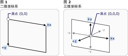
在3-D坐标系中,原点位于呈现区域的中心(即容器中心),x 轴上的正值朝右,但是 y 轴上的正值朝上,z 轴上的正值从原点向外朝向观察者。
照相机
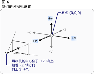
在接下来要介绍的示例中,我们用到的是PerspectiveCamera照相机。
PerspectiveCamera 指定3-D模型到2-D可视图面的投影。此投影包括透视缩短。换言之,PerspectiveCamera
描述各个面均聚集到某个水平点的平截体。对象离摄像机越近就显得越大,离得越远则显得越小。
立方体的创建
就此开始我们的示例。
3D场景
创建一个3D场景。
<Window

        xmlns="http://schemas.microsoft.com/winfx/2006/xaml/presentation"

        xmlns:x="http://schemas.microsoft.com/winfx/2006/xaml"

        xmlns:d="http://schemas.microsoft.com/expression/blend/2008" xmlns:mc="http://schemas.openxmlformats.org/markup-compatibility/2006" mc:Ignorable="d" x:Class="WpfApplication1.MainWindow"

        Title="MainWindow" Height="350" Width="525">

        <Grid>

          <Viewport3D x:Name="Cube">

            </Viewport3D>

       </Grid>

</Window>
照相机
既然是3D场景,那当然得有观察的方向了,也就是照相机了。在3D场景中添加照相机。这里我们使用透视相机PerspectiveCamera 。
       <Grid>

            <Viewport3D>

               <Viewport3D.Camera>

                    <PerspectiveCamera Position="0,0,8" x:Name="camera"></PerspectiveCamera>

                </Viewport3D.Camera>

           </Viewport3D>

        </Grid>
PerspectiveCamera 有很多属性,常用的有以下几个:
| Position | 获取或设置以世界坐标表示的摄像机位置。 (继承自ProjectionCamera。) |
| FieldOfView | 获取或设置一个值,该值表示摄像机的水平视角。 |
| LookDirection | 获取或设置定义摄像机在世界坐标中的拍摄方向的 Vector3D。(继承自ProjectionCamera。) |
| NearPlaneDistance | 获取或设置一个值,该值指定到摄像机近端剪裁平面的摄像机的距离。(继承自ProjectionCamera。) |
| FarPlaneDistance | 获取或设置一个值,该值指定到摄像机远端剪裁平面的摄像机的距离。 (继承自 ProjectionCamera。) |
| UpDirection | 获取或设置定义摄像机向上方向的 Vector3D。(继承自ProjectionCamera。) |
我们现在从基本的做起,只定义了Position的属性。(0,0,8)意思为照相机距离屏幕为8.
模型
照相机也有了,现在就开始定义立方体模型了。大家都知道立方体有6个面,所以我们要定义6个GeometryModel3D。
   <Viewport3D>

            <Viewport3D.Camera>

                <PerspectiveCamera Position="0,0,8" x:Name="camera"></PerspectiveCamera>

            </Viewport3D.Camera>

            <Viewport3D.Children>

              <ModelVisual3D>

                    <ModelVisual3D.Content>

                        <Model3DGroup >

                           <GeometryModel3D>

                                <GeometryModel3D.Material>

                                    <DiffuseMaterial Brush="Green"/>

                                </GeometryModel3D.Material>

                                <GeometryModel3D.Geometry>

                                    <MeshGeometry3D Positions="0,0,0 2,0,0 2,2,0 0,2,0"

TriangleIndices="0,1,2 0,2,3">

                                    </MeshGeometry3D>

                                </GeometryModel3D.Geometry>

                            </GeometryModel3D>

                       </Model3DGroup>

                    </ModelVisual3D.Content>

                </ModelVisual3D>

            </Viewport3D.Children>

        </Viewport3D>
Material是你要为模型填充的纹理,我们使用了绿色来填充。
MeshGeometry3D 用于生成3-D形状的三角形基元。这个说明太抽象,就是说你该定义你的模型框架了。
Positions="0,0,0 2,0,0 2,2,0 0,2,0" 定义了四个点。
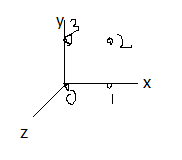
有了这四个点,就应该开始绘制三角形基元,就是要把点串起来。TriangleIndices="0,1,2 0,2,3",意思是将0、1、2这三个顶点连起来组成一个三角形,将0、2、3这三个顶点连起来组成另一个三角。这里有一个技巧,我姑且这样理解,在建立三角形时,如果是逆时针连接顶点,那么建立的三角形就是面向视野的,如果是顺时针连接,就是背向视野的(向外),大家可以试一下TriangleIndices="0,3,2 0,2,1"。这样就绘制出如下图所示的一个面了。
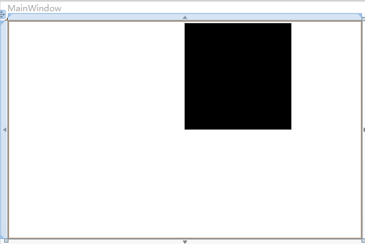
我们定义的是绿色,为什么是黑色的呢。天黑了,当然都是黑色的了!我们缺少光。
 <Viewport3D>

            <Viewport3D.Camera>

                <PerspectiveCamera Position="0,0,8" x:Name="camera"></PerspectiveCamera>

            </Viewport3D.Camera>

            <Viewport3D.Children>

                <ModelVisual3D>

                    <ModelVisual3D.Content>

                        <Model3DGroup >

                            <GeometryModel3D>

                                <GeometryModel3D.Material>

                                    <DiffuseMaterial Brush="Green"/>

                                </GeometryModel3D.Material>

                                <GeometryModel3D.Geometry>

                                    <MeshGeometry3D Positions="0,0,0 2,0,0 2,2,0 0,2,0"

TriangleIndices="0,1,2 0,2,3">

                                    </MeshGeometry3D>

                                </GeometryModel3D.Geometry>

                            </GeometryModel3D>

                        </Model3DGroup>

                    </ModelVisual3D.Content>

                </ModelVisual3D>

               <ModelVisual3D x:Name="light">

                    <ModelVisual3D.Content>

                        <AmbientLight></AmbientLight>

                    </ModelVisual3D.Content>

                </ModelVisual3D>

         </Viewport3D.Children>

        </Viewport3D>
加上红色的那段代码,就有光了,有光了,就变绿了。
接下来给大家几种光,具体的大家可以自己试试。
AmbientLight:它所提供的环境光以一致的方式照亮所有的对象,而与对象的位置或方向无关。
DirectionalLight:像远处的光源那样照亮。 将方向光的 Direction 指定为 Vector3D,但是没有为方向光指定位置。
PointLight:像近处的光源那样照亮。 PointLight 具有一个位置并从该位置投射光。 场景中的对象是根据对象相对于光源的位置和距离而被照亮的。 PointLightBase 公开Range 属性,该属性确定一个距离,超过该距离后模型将无法由光源照亮。 PointLight 还公开了多个衰减属性,这些属性确定光源的亮度如何随距离的增加而减小。 您可以为光源的衰减指定恒定、线性或二次内插算法。
SpotLight:从 PointLight 继承。 Spotlight 的照亮方式与 PointLight 类似,但是它既具有位置又具有方向。 它们在 InnerConeAngle 和 OuterConeAngle 属性所设置的锥形区域(以度为单位指定)中投射光。
好了,至此已经做出来一个面了。那接下来重复上述动作,把其他五个面画全。
  <Grid >

        <Viewport3D Margin="10">

            <Viewport3D.Camera>

                <PerspectiveCamera Position="0,0,8" x:Name="camera"></PerspectiveCamera>

            </Viewport3D.Camera>

            <Viewport3D.Children>

                <ModelVisual3D>

                    <ModelVisual3D.Content>

                        <Model3DGroup >

                            <GeometryModel3D x:Name="F1">

                                <GeometryModel3D.Material>

                                    <DiffuseMaterial Brush="Green"/>

                                </GeometryModel3D.Material>

                                <GeometryModel3D.Geometry>

                                    <MeshGeometry3D Positions="0,0,0 2,0,0 2,2,0 0,2,0"

TriangleIndices="0,2,1 0,3,2">

                                    </MeshGeometry3D>

                                </GeometryModel3D.Geometry>

                            </GeometryModel3D>

                            <GeometryModel3D  x:Name="F2">

                                <GeometryModel3D.Material>

                                    <DiffuseMaterial Brush="Blue"/>

                                </GeometryModel3D.Material>

                                <GeometryModel3D.Geometry>

                                    <MeshGeometry3D Positions="0,0,0 0,0,2 0,2,2 0,2,0"

TriangleIndices="0,1,2 0,2,3">

                                    </MeshGeometry3D>

                                </GeometryModel3D.Geometry>

                            </GeometryModel3D>

                            <GeometryModel3D  x:Name="F3">

                                <GeometryModel3D.Material>

                                    <DiffuseMaterial Brush="Gray"/>

                                </GeometryModel3D.Material>

                                <GeometryModel3D.Geometry>

                                    <MeshGeometry3D Positions="0,0,0 0,0,2 2,0,2 2,0,0"

TriangleIndices="0,2,1 0,3,2">

                                    </MeshGeometry3D>

                                </GeometryModel3D.Geometry>

                            </GeometryModel3D>

                            <GeometryModel3D  x:Name="F4">

                                <GeometryModel3D.Material>

                                    <DiffuseMaterial Brush="Bisque"/>

                                </GeometryModel3D.Material>

                                <GeometryModel3D.Geometry>

                                    <MeshGeometry3D Positions="2,0,0 2,2,0 2,2,2 2,0,2"

TriangleIndices="0,1,2 0,2,3">

                                    </MeshGeometry3D>

                                </GeometryModel3D.Geometry>

                            </GeometryModel3D>

                            <GeometryModel3D  x:Name="F5">

                                <GeometryModel3D.Material>

                                    <DiffuseMaterial Brush="Yellow"/>

                                </GeometryModel3D.Material>

                                <GeometryModel3D.Geometry>

                                    <MeshGeometry3D Positions="0,2,2 2,2,2 2,2,0 0,2,0"

TriangleIndices="0,1,2 0,2,3">

                                    </MeshGeometry3D>

                                </GeometryModel3D.Geometry>

                            </GeometryModel3D>

                            <GeometryModel3D  x:Name="F6">

                                <GeometryModel3D.Material>

                                    <DiffuseMaterial Brush="Red"/>

                                </GeometryModel3D.Material>

                                <GeometryModel3D.Geometry>

                                    <MeshGeometry3D Positions="0,2,2 2,2,2 0,0,2 2,0,2"

TriangleIndices="0,2,3 0,3,1">

                                    </MeshGeometry3D>

                                </GeometryModel3D.Geometry>

                            </GeometryModel3D>

                        </Model3DGroup>

                    </ModelVisual3D.Content>

                </ModelVisual3D>

                <ModelVisual3D x:Name="light">

                    <ModelVisual3D.Content>

                        <AmbientLight></AmbientLight>

                    </ModelVisual3D.Content>

                </ModelVisual3D>

            </Viewport3D.Children>

        </Viewport3D>

    </Grid>
至此,立方体模型已经建立。大家可以用blend(点击XAML中的ModelVisual3D节点,出现三维坐标),来回转动试试!
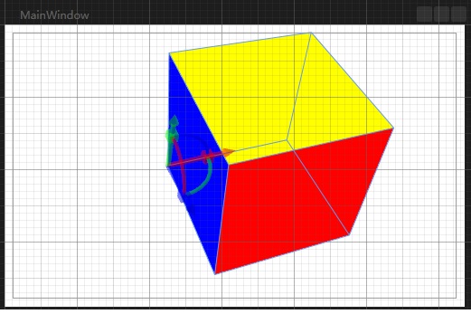
上面那个因为每个面的填充色不同,所以分为6个面来构造立方体。
那么如果一个所有面都是绿色的立方体如何构建呢,还要那么麻烦吗。我们理解到Position代表顶点,一个立方体有8个顶点。那么从这8个顶点来构建立方体可以吗?
<Grid >

        <Viewport3D Margin="10">

            <Viewport3D.Camera>

                <PerspectiveCamera Position="0,0,8" x:Name="camera"></PerspectiveCamera>

            </Viewport3D.Camera>

            <Viewport3D.Children>

                <ModelVisual3D>

                    <ModelVisual3D.Content>

                           <GeometryModel3D x:Name="F1">

                                <GeometryModel3D.Material>

                                    <DiffuseMaterial Brush="Green"/>

                                </GeometryModel3D.Material>

                                <GeometryModel3D.Geometry>

                                    <MeshGeometry3D Positions="0,0,0 2,0,0 2,2,0 0,2,0 0,2,2 0,0,2 2,0,2 2,2,2"

TriangleIndices="0,2,1 0,3,2 0,4,3 0,5,4 0,1,6 0,6,5 3,4,7 3,7,2 4,5,6 4,6,7 7,6,1 7,1,2">

                                    </MeshGeometry3D>

                                </GeometryModel3D.Geometry>

                            </GeometryModel3D>

                   </ModelVisual3D.Content>

                </ModelVisual3D>

                <ModelVisual3D x:Name="light">

                    <ModelVisual3D.Content>

                        <AmbientLight></AmbientLight>

                    </ModelVisual3D.Content>

                </ModelVisual3D>

            </Viewport3D.Children>

        </Viewport3D>

    </Grid>
blend中查看图如下(经过变换的):
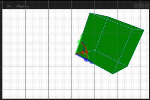
好了,立方体的构造到此结束。
p.s 不容易呀,第一次自己写博客,不好了别喷,费了我俩小时!我也是刚学这个WPF的3D的,后续进行动画添加,3D控制了,我也会坚持记录下来!新手上路,大小神莫笑哈!
WPF3D学习,立方体的绘制的更多相关文章
- Direct3D11学习:(七)绘图基础——彩色立方体的绘制
转载请注明出处:http://www.cnblogs.com/Ray1024 一.概述 在前面的几篇文章中,我们详细介绍了Direct3D渲染所需要的数学基础和渲染管道理论知识.从这篇文章开始,我们就 ...
- HTML5学习总结——canvas绘制象棋(canvas绘图)
一.HTML5学习总结——canvas绘制象棋 1.第一次:canvas绘制象棋(笨方法)示例代码: <!DOCTYPE html> <html> <head> & ...
- iOS学习——Quartz2D学习之UIKit绘制
iOS学习——Quartz2D学习之UIKit绘制 1.总述 在IOS中绘图技术主要包括:UIKit.Quartz 2D.Core Animation和OpenGL ES.其中Core Animati ...
- OpenGL入门学习 课程 (三) 绘制几何图形的一些细节问题
http://oulehui.blog.163.com/blog/static/79614698201191832753312/ 先回顾一下我们都学习了些什么: 第一课,编写第一个OpenGL程序第二 ...
- Unity3D学习笔记2——绘制一个带纹理的面
目录 1. 概述 2. 详论 2.1. 网格(Mesh) 2.1.1. 顶点 2.1.2. 顶点索引 2.2. 材质(Material) 2.2.1. 创建材质 2.2.2. 使用材质 2.3. 光照 ...
- Win32汇编学习(5):绘制文本2
这次我们将学习有关文本的诸多属性如字体和颜色等. 理论: Windows 的颜色系统是用RGB值来表示的,R 代表红色,G 代表绿色,B 代表蓝色.如果您想指定一种颜色就必须给该颜色赋相关的 RGB ...
- Win32汇编学习(4):绘制文本
这次,我们将学习如何在窗口的客户区"绘制"字符串.我们还将学习关于"设备环境"的概念. 理论: "绘制"字符串 Windows 中的文本是一 ...
- Reshape以及向量机分类学习和等高线绘制代码
首先科普一下python里面对于数组的处理,就是如果获取数组大小,以及数组元素数量,这个概念是不一样的,就是一个size和len处理不用.老规矩,上代码: arr2 = np.array([-19.5 ...
- WebGL学习笔记二——绘制基本图元
webGL的基本图元点.线.三角形 gl.drawArrays(mode, first,count) first,代表从第几个点开始绘制即顶点的起始位置 count,代表绘制的点的数量. mode,代 ...
随机推荐
- RBAC用户角色权限设计方案
RBAC(Role-Based Access Control,基于角色的访问控制),就是用户通过角色与权限进行关联.简单地说,一个用户拥有若干角色,每一个角色拥有若干权限.这样,就构造成“用 户-角色 ...
- Lambda高手之路第二部分
转http://www.cnblogs.com/lazycoding/archive/2013/01/06/2847579.html 闭包的影响 为了展示闭包的影响,我们看下面这个例子. var bu ...
- [Android学习笔记]ListView中含有Button导致无法响应onItemClick回调的解决办法
转自:http://www.cnblogs.com/eyu8874521/archive/2012/10/17/2727882.html 问题描述: 当ListView的Item中的控件只是一些展示类 ...
- 用VBA宏从一个工作薄复制内容到另一个工作薄
我们项目管理有两个工作薄,一个里面有多个表,每天建一个,记录当天项目,另一个工作薄,有多个表,其中一个是所有项目汇总. 以前都是第一个工作薄一个表做完,再复制粘贴到第二个工作薄的汇总表中. 写了个VB ...
- Android中使用SurfaceView和Canvas来绘制动画
事实上每一个View中都有Canvas能够用来绘制动画.仅仅须要在这个View中重载onDraw()方法就能够,可是SurfaceView类是一个专门用来制动动画的类. Canvas(中文叫做&quo ...
- hdu3329(2次dfs)
传送门:The Flood 题意:当水的高度升为多少的时候,能够将这块区域分为两个部分. 分析:枚举高度,先从外围开始一次dfs,将水能淹没的标记,然后看非标记的是否已分为多块. #include&l ...
- Java NIO的性能
最近调研了一下mina和netty框架的性能,主要是想了解java nio在单机能支持多少长连接. 首先,mina的qq群有同学反映说单机支持3w长连接是没问题的 其次,http://amix.dk/ ...
- TypeError: Cannot read property 'style' of null 错误解决
错误信息例如以下: JSP代码例如以下: <c:if test ="${not empty excelErrors}"> <div id="excelE ...
- SE 2014年4月30日
如图配置: SW1 SW2 SW3 SW4组成一环型网络 Sw2 和Sw4个存在两业务vlan(vlan 10 和vlan 20) 1.Smart Link 组1 的引用实例1(绑定VLAN 10 ) ...
- Yii学习笔记之三(在windows 上安装 advanced )
首先说一下下载地址: http://www.yiiframework.com/download/ 然后将下载下来的文件进行解压到 你指定的文件夹 解压过程中假设报什么错误 直接忽略掉 我的解压文件夹是 ...
