Network基础(五):配置静态路由、配置浮动路由、配置多路由的静态路由、配置默认路由
一、配置静态路由
目标:
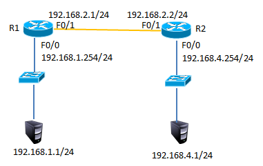
配置路由接口IP地址并通过静态路由的配置实现全网的互通。
方案:
按如下网络拓扑配置接口IP地址并通过静态路由的配置实现全网的互通如下图所示:
步骤:
步骤一:配置静态路由
1)R1上配置接口IP
R1(config)#interface fastEthernet 0/0
R1(config-if)#ip address 192.168.1.254 255.255.255.0
R1(config-if)#no shutdown
R1(config-if)#exit
R1(config)#interface fastEthernet 0/1
R1(config-if)#ip address 192.168.2.1 255.255.255.0
R1(config-if)#no shutdown
2)R2上配置接口IP
R2(config)#interface fastEthernet 0/1
R2(config-if)#ip address 192.168.2.2 255.255.255.0
R2(config-if)#no shutdown
R2config-if)#exit
R2(config)#interface fastEthernet 0/0
R2(config-if)#ip address 192.168.4.254 255.255.255.0
R2(config-if)#no shutdown
3)R1上添加静态路由
R1(config)#ip route 192.168.4.0 255.255.255.0 192.168.2.2
4)R1上查看路由表
R1#show ip route
Codes: C - connected, S - static, I - IGRP, R - RIP, M - mobile, B - BGP
D - EIGRP, EX - EIGRP external, O - OSPF, IA - OSPF inter area
N1 - OSPF NSSA external type 1, N2 - OSPF NSSA external type 2
E1 - OSPF external type 1, E2 - OSPF external type 2, E - EGP
i - IS-IS, L1 - IS-IS level-1, L2 - IS-IS level-2, ia - IS-IS inter area
* - candidate default, U - per-user static route, o - ODR
P - periodic downloaded static route
Gateway of last resort is not set
C 192.168.1.0/24 is directly connected, FastEthernet0/0
C 192.168.2.0/24 is directly connected, FastEthernet0/1
S 192.168.4.0/24 [1/0] via 192.168.2.2 //S表示静态路由
5)R2上添加静态路由
R2(config)#ip route 192.168.1.0 255.255.255.0 192.168.2.1
6)R2上查看路由条目
R2#show ip route
Codes: C - connected, S - static, I - IGRP, R - RIP, M - mobile, B - BGP
D - EIGRP, EX - EIGRP external, O - OSPF, IA - OSPF inter area
N1 - OSPF NSSA external type 1, N2 - OSPF NSSA external type 2
E1 - OSPF external type 1, E2 - OSPF external type 2, E - EGP
i - IS-IS, L1 - IS-IS level-1, L2 - IS-IS level-2, ia - IS-IS inter area
* - candidate default, U - per-user static route, o - ODR
P - periodic downloaded static route
Gateway of last resort is not set
S 192.168.1.0/24 [1/0] via 192.168.2.1 //S表示静态路由
C 192.168.2.0/24 is directly connected, FastEthernet0/1
C 192.168.3.0/24 is directly connected, FastEthernet0/0
7)配置PC1的IP地址为192.168.1.1,网关为192.168.1.254
8)配置PC2的IP地址为192.168.4.1,网关为192.168.4.254
9)测试网络连通性,PC1 ping 192.168.4.1
PC>ping 192.168.4.1
Pinging 192.168.4.1 with 32 bytes of data:
Reply from 192.168.4.1: bytes=32 time=1ms TTL=126
Reply from 192.168.4.1: bytes=32 time=11ms TTL=126
Reply from 192.168.4.1: bytes=32 time=10ms TTL=126
Reply from 192.168.4.1: bytes=32 time=11ms TTL=126
Ping statistics for 192.168.4.1:
Packets: Sent = 4, Received = 4, Lost = 0 (0% loss),
Approximate round trip times in milli-seconds:
Minimum = 1ms, Maximum = 11ms, Average = 8ms
二、配置浮动路由
目标:
配置浮动静态路由
方案:
按如下网络拓扑配置接口IP地址配置浮动路由实现链路的冗余,如下图所示

步骤:
步骤一:配置静态路由并添加模块
1)R1上配置接口IP
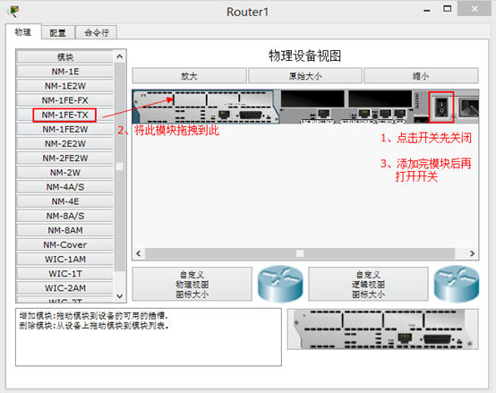
在以上静态路由实验的基础上,先分别进入R1与R2的特权模式输入write命令保存配置信息,然后分别进入R1与R2的物理配置界面,点击开关按钮关闭路由器,添加NM-1FE-TX模块并再次点击开关按钮,如下图所示。
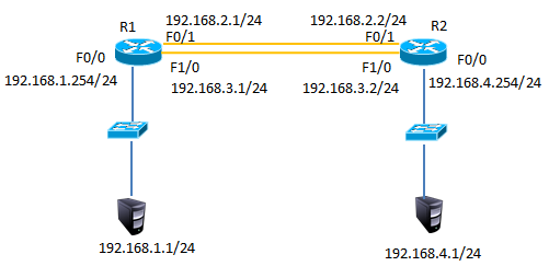
2)添加模块后将R1的F1/0接口连接到R2的F1/0接口修改拓扑如下图所示:
3)配置R1的F1/0接口IP
R1(config)#interface fastEthernet 1/0
R1(config-if)#ip address 192.168.3.1 255.255.255.0
R1(config-if)#no shutdown
4)配置R2的F1/0接口IP
R2(config)#interface fastEthernet 1/0
R2(config-if)#ip address 192.168.3.2 255.255.255.0
R2(config-if)#no shutdown
5)R1上添加静态浮动路由
R1(config)#ip route 192.168.4.0 255.255.255.0 192.168.3.2 50 //管理距离50
6)R2上添加静态浮动路由
R2(config)#ip route 192.168.1.0 255.255.255.0 192.168.3.1 50 //管理距离50
7)R1上查看路由表
R1#show ip route
Codes: C - connected, S - static, I - IGRP, R - RIP, M - mobile, B - BGP
D - EIGRP, EX - EIGRP external, O - OSPF, IA - OSPF inter area
N1 - OSPF NSSA external type 1, N2 - OSPF NSSA external type 2
E1 - OSPF external type 1, E2 - OSPF external type 2, E - EGP
i - IS-IS, L1 - IS-IS level-1, L2 - IS-IS level-2, ia - IS-IS inter area
* - candidate default, U - per-user static route, o - ODR
P - periodic downloaded static route
Gateway of last resort is not set
C 192.168.1.0/24 is directly connected, FastEthernet0/0
C 192.168.2.0/24 is directly connected, FastEthernet0/1
C 192.168.3.0/24 is directly connected, FastEthernet1/0
S 192.168.4.0/24 [1/0] via 192.168.2.2 //只有下一跳为192.168.2.2的静态路由
8)禁用F/01接口
R1(config)#interface fastEthernet 0/1
R1(config-if)#shutdown
9)R1上查看路由表
C 192.168.1.0/24 is directly connected, FastEthernet0/0
S 192.168.4.0/24 [50/0] via 192.168.3.2//下一跳接口为192.168.4.2的路由生效
C 192.168.4.0/24 is directly connected, FastEthernet1/0
10)测试网络连通性,PC1 ping 192.168.4.1
PC>ping 192.168.4.1
Pinging 192.168.4.1 with 32 bytes of data:
Reply from 192.168.4.1: bytes=32 time=0ms TTL=126
Reply from 192.168.4.1: bytes=32 time=10ms TTL=126
Reply from 192.168.4.1: bytes=32 time=11ms TTL=126
Reply from 192.168.4.1: bytes=32 time=1ms TTL=126
Ping statistics for 192.168.4.1:
Packets: Sent = 4, Received = 4, Lost = 0 (0% loss),
Approximate round trip times in milli-seconds:
Minimum = 0ms, Maximum = 11ms, Average = 5ms
三、配置多路由的静态路由
目标:
配置多路由的静态路由
方案:
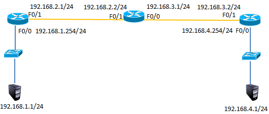
网络环境及IP地址规划,如下图所示

步骤:
步骤一:配置路由IP和静态路由
1) R1上配置接口IP
Router(config)#interface fastEthernet 0/0
R1(config-if)#ip address 192.168.1.254 255.255.255.0
R1(config-if)#no shutdown
R1(config-if)#exit
R1(config)#interface fastEthernet 0/1
R1(config-if)#ip address 192.168.2.1 255.255.255.0
R1(config-if)#no shutdown
2)R2上配置接口IP
R2(config)#interface f0/1
R2(config-if)#ip address 192.168.2.2 255.255.255.0
R2(config-if)#no shutdown
R2(config-if)#exit
R2(config)#interface fastEthernet 0/0
R2(config-if)#ip address 192.168.3.1 255.255.255.0
R2(config-if)#no shutdown
3)R3上配置接口IP
R3(config)#interface fastEthernet 0/1
R3(config-if)#ip address 192.168.3.2 255.255.255.0
R3(config-if)#no shutdown
R3(config-if)#exit
R3(config)#interface fastEthernet 0/0
R3(config-if)#ip address 192.168.4.254 255.255.255.0
R3(config-if)#no shutdown
4)R1、R2、R3上分别添加静态路由
R1(config)#ip route 192.168.3.0 255.255.255.0 192.168.2.2
R1(config)#ip route 192.168.4.0 255.255.255.0 192.168.2.2
R2(config)#ip route 192.168.1.0 255.255.255.0 192.168.2.1
R2(config)#ip route 192.168.4.0 255.255.255.0 192.168.3.2
R3(config)#ip route 192.168.1.0 255.255.255.0 192.168.3.1
R3(config)#ip route 192.168.2.0 255.255.255.0 192.168.3.1
5)R1上查看路由表
R1#show ip route
Codes: C - connected, S - static, I - IGRP, R - RIP, M - mobile, B - BGP
D - EIGRP, EX - EIGRP external, O - OSPF, IA - OSPF inter area
N1 - OSPF NSSA external type 1, N2 - OSPF NSSA external type 2
E1 - OSPF external type 1, E2 - OSPF external type 2, E - EGP
i - IS-IS, L1 - IS-IS level-1, L2 - IS-IS level-2, ia - IS-IS inter area
* - candidate default, U - per-user static route, o - ODR
P - periodic downloaded static route
Gateway of last resort is not set
C 192.168.1.0/24 is directly connected, FastEthernet0/0
C 192.168.2.0/24 is directly connected, FastEthernet0/1
S 192.168.3.0/24 [1/0] via 192.168.2.2 //静态路由
S 192.168.4.0/24 [1/0] via 192.168.2.2 //静态路由
6)R2上查看路由表
R2#show ip route
Codes: C - connected, S - static, I - IGRP, R - RIP, M - mobile, B - BGP
D - EIGRP, EX - EIGRP external, O - OSPF, IA - OSPF inter area
N1 - OSPF NSSA external type 1, N2 - OSPF NSSA external type 2
E1 - OSPF external type 1, E2 - OSPF external type 2, E - EGP
i - IS-IS, L1 - IS-IS level-1, L2 - IS-IS level-2, ia - IS-IS inter area
* - candidate default, U - per-user static route, o - ODR
P - periodic downloaded static route
Gateway of last resort is not set
S 192.168.1.0/24 [1/0] via 192.168.2.1 //静态路由
C 192.168.2.0/24 is directly connected, FastEthernet0/1
C 192.168.3.0/24 is directly connected, FastEthernet0/0
S 192.168.4.0/24 [1/0] via 192.168.3.2 //静态路由
7)R3上查看路由表
R3#show ip route
Codes: C - connected, S - static, I - IGRP, R - RIP, M - mobile, B - BGP
D - EIGRP, EX - EIGRP external, O - OSPF, IA - OSPF inter area
N1 - OSPF NSSA external type 1, N2 - OSPF NSSA external type 2
E1 - OSPF external type 1, E2 - OSPF external type 2, E - EGP
i - IS-IS, L1 - IS-IS level-1, L2 - IS-IS level-2, ia - IS-IS inter area
* - candidate default, U - per-user static route, o - ODR
P - periodic downloaded static route
Gateway of last resort is not set
S 192.168.1.0/24 [1/0] via 192.168.3.1 //静态路由
S 192.168.2.0/24 [1/0] via 192.168.3.1 //静态路由
C 192.168.3.0/24 is directly connected, FastEthernet0/1
C 192.168.4.0/24 is directly connected, FastEthernet0/0
8)按图-4配置PC的IP地址
9)测试网络连通性,PC1 ping 192.168.2.2、192.168.3.1、192.168.3.2、192.168.4.1
PC>ping 192.168.2.2 //ping 192.168.2.2
Pinging 192.168.2.2 with 32 bytes of data:
Reply from 192.168.2.2: bytes=32 time=0ms TTL=254
Reply from 192.168.2.2: bytes=32 time=0ms TTL=254
Reply from 192.168.2.2: bytes=32 time=0ms TTL=254
Reply from 192.168.2.2: bytes=32 time=0ms TTL=254
Ping statistics for 192.168.2.2:
Packets: Sent = 4, Received = 4, Lost = 0 (0% loss),
Approximate round trip times in milli-seconds:
Minimum = 0ms, Maximum = 0ms, Average = 0ms
PC>ping 192.168.3.1 //ping 192.168.3.1
Pinging 192.168.3.1 with 32 bytes of data:
Reply from 192.168.3.1: bytes=32 time=0ms TTL=254
Reply from 192.168.3.1: bytes=32 time=3ms TTL=254
Reply from 192.168.3.1: bytes=32 time=0ms TTL=254
Reply from 192.168.3.1: bytes=32 time=0ms TTL=254
Ping statistics for 192.168.3.1:
Packets: Sent = 4, Received = 4, Lost = 0 (0% loss),
Approximate round trip times in milli-seconds:
Minimum = 0ms, Maximum = 3ms, Average = 0ms
PC>ping 192.168.3.2 //ping 192.168.3.2
Pinging 192.168.3.2 with 32 bytes of data:
Reply from 192.168.3.2: bytes=32 time=0ms TTL=253
Reply from 192.168.3.2: bytes=32 time=12ms TTL=253
Reply from 192.168.3.2: bytes=32 time=0ms TTL=253
Reply from 192.168.3.2: bytes=32 time=12ms TTL=253
Ping statistics for 192.168.3.2:
Packets: Sent = 4, Received = 4, Lost = 0 (0% loss),
Approximate round trip times in milli-seconds:
Minimum = 0ms, Maximum = 12ms, Average = 6ms
PC>ping 192.168.4.1 //ping 192.168.4.1
Pinging 192.168.4.1 with 32 bytes of data:
Reply from 192.168.4.1: bytes=32 time=0ms TTL=125
Reply from 192.168.4.1: bytes=32 time=10ms TTL=125
Reply from 192.168.4.1: bytes=32 time=0ms TTL=125
Reply from 192.168.4.1: bytes=32 time=22ms TTL=125
Ping statistics for 192.168.4.1:
Packets: Sent = 4, Received = 4, Lost = 0 (0% loss),
Approximate round trip times in milli-seconds:
Minimum = 0ms, Maximum = 22ms, Average = 8ms
四、配置默认路由
目标:
配置默认路由
方案:
网络环境及IP地址规划,如下图所示
步骤:
1)在案例3基础上删除R1与R3的静态路由
R1(config)#no ip route 192.168.3.0 255.255.255.0 192.168.2.2
R1(config)#no ip route 192.168.4.0 255.255.255.0 192.168.2.2
R3(config)#no ip route 192.168.1.0 255.255.255.0 192.168.3.1
R3(config)#no ip route 192.168.2.0 255.255.255.0 192.168.3.1
2)R1、R3添加默认路由
R1(config)#ip route 0.0.0.0 0.0.0.0 192.168.2.2
R3(config)#ip route 0.0.0.0 0.0.0.0 192.168.3.1
12)R1上查看路由表
R1#show ip route
Codes: C - connected, S - static, I - IGRP, R - RIP, M - mobile, B - BGP
D - EIGRP, EX - EIGRP external, O - OSPF, IA - OSPF inter area
N1 - OSPF NSSA external type 1, N2 - OSPF NSSA external type 2
E1 - OSPF external type 1, E2 - OSPF external type 2, E - EGP
i - IS-IS, L1 - IS-IS level-1, L2 - IS-IS level-2, ia - IS-IS inter area
* - candidate default, U - per-user static route, o - ODR
P - periodic downloaded static route
Gateway of last resort is 192.168.2.2 to network 0.0.0.0
C 192.168.1.0/24 is directly connected, FastEthernet0/0
C 192.168.2.0/24 is directly connected, FastEthernet0/1
S* 0.0.0.0/0 [1/0] via 192.168.2.2 //默认路由
3)R1、R3上查看路由表
R1#show ip route
Codes: C - connected, S - static, I - IGRP, R - RIP, M - mobile, B - BGP
D - EIGRP, EX - EIGRP external, O - OSPF, IA - OSPF inter area
N1 - OSPF NSSA external type 1, N2 - OSPF NSSA external type 2
E1 - OSPF external type 1, E2 - OSPF external type 2, E - EGP
i - IS-IS, L1 - IS-IS level-1, L2 - IS-IS level-2, ia - IS-IS inter area
* - candidate default, U - per-user static route, o - ODR
P - periodic downloaded static route
Gateway of last resort is 192.168.3.1 to network 0.0.0.0
C 192.168.1.0/24 is directly connected, FastEthernet0/0
C 192.168.2.0/24 is directly connected, FastEthernet0/1
S* 0.0.0.0/0 [1/0] via 192.168.2.2 //默认路由
R3#show ip route
Codes: C - connected, S - static, I - IGRP, R - RIP, M - mobile, B - BGP
D - EIGRP, EX - EIGRP external, O - OSPF, IA - OSPF inter area
N1 - OSPF NSSA external type 1, N2 - OSPF NSSA external type 2
E1 - OSPF external type 1, E2 - OSPF external type 2, E - EGP
i - IS-IS, L1 - IS-IS level-1, L2 - IS-IS level-2, ia - IS-IS inter area
* - candidate default, U - per-user static route, o - ODR
P - periodic downloaded static route
Gateway of last resort is 192.168.3.1 to network 0.0.0.0
C 192.168.3.0/24 is directly connected, FastEthernet0/1
C 192.168.4.0/24 is directly connected, FastEthernet0/0
S* 0.0.0.0/0 [1/0] via 192.168.3.1 //默认路由
4)测试网络连通性,PC1 ping 192.168.4.1
PC>ping 192.168.4.1
Pinging 192.168.4.1 with 32 bytes of data:
Reply from 192.168.4.1: bytes=32 time=1ms TTL=125
Reply from 192.168.4.1: bytes=32 time=0ms TTL=125
Reply from 192.168.4.1: bytes=32 time=14ms TTL=125
Reply from 192.168.4.1: bytes=32 time=14ms TTL=125
Ping statistics for 192.168.4.1:
Packets: Sent = 4, Received = 4, Lost = 0 (0% loss),
Approximate round trip times in milli-seconds:
Minimum = 0ms, Maximum = 14ms, Average = 7ms = 0ms,平均 = 0ms
Network基础(五):配置静态路由、配置浮动路由、配置多路由的静态路由、配置默认路由的更多相关文章
- Go的http包中默认路由匹配规则
# 一.执行流程 首先我们构建一个简单http server: ```go package main import ( "log" "net/http" ) f ...
- Cisco基础(五):配置静态NAT、配置端口映射、配置动态NAT、PAT配置、办公区Internet的访问
一.配置静态NAT 目标: 随着接入Internet的计算机数量的不断猛增,IP地址资源也就愈加显得捉襟见肘.事实上,除了中国教育和科研计算机网(CERNET)外,一般用户几乎申请不到整段的C类IP地 ...
- IT菜鸟之路由器基础配置(静态、动态、默认路由)
路由器:连接不同网段的设备 企业级路由和家用级路由的区别: 待机数量不同(待机量) 待机量:同时接通的终端设备的数量 待机量的值越高,路由的性能越好 别墅级路由,表示信号好,和性能无关 交换机:背板带 ...
- Linux基础五:网络配置与管理
五.网络配置与管理 1.网络知识 2.命令 ifconfig命令 <=> ip addr show 命令--查看本地所有网卡配置信息 ens32:本地以太网网卡,lo:本地回环网卡 ...
- Network基础(三):网线的制作、交换机基本命令模式、交换机命令行基本配置、交换机的密码设置
一.网线的制作 目标: 在常见的计算机网络中,网线主要用来连接计算机与交换机(或宽带路由器).交换机与交换机.交换机与路由器,以及需要连网的其他各种设备.网线的制作与测试是作为网络管理员的一个入门技能 ...
- 默认路由、RIPv2、OSPF、EIGRP配置(全网全通)
1:默认路由 遇到问题:给r2配置向右的单项默认路由,通过PC1去ping主机PC2,一直显示Request timed out, 解决方法:r2配置如下: r2(config)#ip route 0 ...
- 【网络】默认路由、RIPv2、OSPF、EIGRP配置(全网全通)
1:默认路由 遇到问题:给r2配置向右的单项默认路由,通过PC1去ping主机PC2,一直显示Request timed out, 解决方法:r2配置如下: r2(config)#ip route 0 ...
- 并发编程概述 委托(delegate) 事件(event) .net core 2.0 event bus 一个简单的基于内存事件总线实现 .net core 基于NPOI 的excel导出类,支持自定义导出哪些字段 基于Ace Admin 的菜单栏实现 第五节:SignalR大杂烩(与MVC融合、全局的几个配置、跨域的应用、C/S程序充当Client和Server)
并发编程概述 前言 说实话,在我软件开发的头两年几乎不考虑并发编程,请求与响应把业务逻辑尽快完成一个星期的任务能两天完成绝不拖三天(剩下时间各种浪),根本不会考虑性能问题(能接受范围内).但随着工 ...
- Centos双网卡配置默认路由
Centos6.5 双网卡,我们只需要一个默认路由,如果两个都有或都没有会有一系列的问题 [root@centos]# vi /etc/sysconfig/network修改以下内容NETWORKIN ...
随机推荐
- CSP-S2019退役记/爆内存记
DAY 0 准备出发. 出发前教练说遇到事不慌,打电话,又听教练说了说历年赶车经历. 然后这趟路上居然没有什么大事. 在车上有些闲,于是就和其他人聊了会天,聊着聊着没意思,就用手机翻博客园. 这样就不 ...
- python 简单抓取网页并写入excel实例
# -*- coding: UTF-8 -*- import requests from bs4 import BeautifulSoup import xlwt import time #获取第一页 ...
- codeforces 111A/112C Petya and Inequiations
题目:Petya and Inequiations传送门: http://codeforces.com/problemset/problem/111/A http://codeforces.com/p ...
- 22 October in 614
Contest A. defile struct 自定义排序.按照题意抽象成模型模拟就可以了. 自定义排序核心代码: struct node { int x, id; } d[1000003]; bo ...
- MySQL复制表结构和内容到另一个表中
一:(低版本的mysql不支持,mysql4.0.25 不支持,mysql5已经支持了)1.复制表结构到新表CREATE TABLE 新表LIKE 旧表 2.复制旧表的数据到新表(假设两个表结构一样) ...
- Bootstarp-源码分析-alert.js v3.x和v4.x的对比
一些概念 1. 使用 data-api 调用 就是给所有带有data-dismiss="alert"的元素绑定点击事件 v3.x: $(document).on('click.bs ...
- 斯坦福【概率与统计】课程笔记(五):EDA | 箱线图
介绍箱线图之前,需要先介绍若干个其需要的术语 min:整个样本的最小值 max:整个样本的最大值 Range:即整个样本的取值范围,Range = max - min Inter-Quartile R ...
- CSS中让背景图片居中且不平铺
background:url(../images/logo.jpg) no-repeat center ;
- lerna----一个强大的专注组件库的管理工具
最近在看关于lerna的资料,没有中文版api.简书上有一篇文章半英半汉,可以撸来看看. http://www.jianshu.com/p/63ec67445b0f
- 2019年RTC大会记录
小编近期在研究webRTC点对点通信技术,怀着学习的心态参加了2019年RTC大会,对所见所闻做下记录,不对的地方还请批评指正! 这次热门的话题是5G.WebRTC.AI对图像.音视频的相关处理,思科 ...