cordic算法的verilog实现及modelsim仿真
1. 算法介绍
CORDIC(Coordinate Rotation Digital Computer)算法即坐标旋转数字计算方法,是J.D.Volder1于1959年首次提出,主要用于三角函数、双曲线、指数、对数的计算。该算法通过基本的加和移位运算代替乘法运算,使得矢量的旋转和定向的计算不再需要三角函数、乘法、开方、反三角、指数等函数,计算向量长度并能把直角坐标系转换为极坐标系。因为Cordic 算法只用了移位和加法,很容易用纯硬件来实现,非常适合FPGA实现。
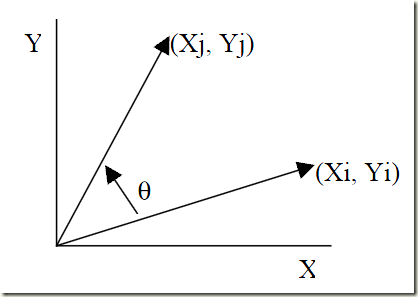
CORDIC算法完成坐标或向量的平面旋转(下图以逆时针旋转为例)。

旋转后,可得如下向量:

旋转的角度θ经过多次旋转得到的(步步逼近,接近二分查找法),每次旋转一小角度。单步旋转定义如下公式:

公式(2)提取cosθ,可修改为:

修改后的公式把乘法次数从4次改为3次,剩下的乘法运算可以通过选择每次旋转的角度去除,将每一步的正切值选为2的指数(二分查找法),除以2的指数可以通过右移操作完成(verilog)。
每次旋转的角度可以表示为:

所有迭代角度累加值等于最终需要的旋转角度θ:

这里Sn为1或者-1,根据旋转方向确定(后面有确定方法,公式(15)),顺时针为-1,逆时针为1。

可以得到如下公式:

结合公式(3)和(7),得到公式(8):

到这里,除了余弦值这个系数,算法只要通过简单的移位和加法操作完成。而这个系数可以通过预先计算最终值消掉。首先重新重写这个系数如下:

第二步计算所有的余弦值并相乘,这个值K称为增益系数。

由于K值是常量,我们可以先忽略它。


到这里我们发现,算法只剩下移位和加减法,这就非常适合硬件实现了,为硬件快速计算三角函数提供了一种新的算法。在进行迭代运算时,需要引入一个新的变量Z,表示需要旋转的角度θ中还没有旋转的角度。

这里,我们可以把前面提到确定旋转方向的方法介绍了,就是通过这个变量Z的符号确定。


通过公式(5)和(15),将未旋转的角度变为0。
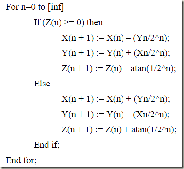
一个类编程风格的结构如下,反正切值是预先计算好的。

1.1 旋转模式
旋转模式下,CORDIC算法驱动Z变为0,结合公式(13)和(16),算法的核心计算如下:

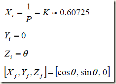
一种特殊情况是,另初始值如下:

因此,旋转模式下CORDIC算法可以计算一个输入角度的正弦值和余弦值。
1.2 向量模式
向量模式下,有两种特例:

因此,向量模式下CORDIC算法可以用来计算输入向量的模和反正切,也能开方计算,并可以将直角坐标转换为极坐标。
算法介绍:http://en.wikipedia.org/wiki/Cordic,http://blog.csdn.net/liyuanbhu/article/details/8458769
2. matlab实现
根据算法原理,利用维基百科中给的程序,在matlab中跑了一遍,对算法有了一定程度的了解。
程序如下:
 function v = cordic(beta,n)

 % This function computes v = [cos(beta), sin(beta)] (beta in radians)

 % using n iterations. Increasing n will increase the precision.

 if beta < -pi/ || beta > pi/

     if beta <

         v = cordic(beta + pi, n);

     else

         v = cordic(beta - pi, n);

     end

     v = -v; % flip the sign for second or third quadrant

 %     return

 end

 % Initialization of tables of constants used by CORDIC

 % need a table of arctangents of negative powers of two, in radians:

 % angles = atan(.^-(:));

 angles =  [  ...

     0.78539816339745   0.46364760900081   0.24497866312686   0.12435499454676 ...

     0.06241880999596   0.03123983343027   0.01562372862048   0.00781234106010 ...

     0.00390623013197   0.00195312251648   0.00097656218956   0.00048828121119 ...

     0.00024414062015   0.00012207031189   0.00006103515617   0.00003051757812 ...

     0.00001525878906   0.00000762939453   0.00000381469727   0.00000190734863 ...

     0.00000095367432   0.00000047683716   0.00000023841858   0.00000011920929 ...

     0.00000005960464   0.00000002980232   0.00000001490116   0.00000000745058 ];

 % and a table of products of reciprocal lengths of vectors [, ^-2j]:

 Kvalues = [ ...

     0.70710678118655   0.63245553203368   0.61357199107790   0.60883391251775 ...

     0.60764825625617   0.60735177014130   0.60727764409353   0.60725911229889 ...

     0.60725447933256   0.60725332108988   0.60725303152913   0.60725295913894 ...

     0.60725294104140   0.60725293651701   0.60725293538591   0.60725293510314 ...

     0.60725293503245   0.60725293501477   0.60725293501035   0.60725293500925 ...

     0.60725293500897   0.60725293500890   0.60725293500889   0.60725293500888 ];

 Kn = Kvalues(min(n, length(Kvalues)));

 % Initialize loop variables:

 v = [;]; % start with -vector cosine and sine of zero

 poweroftwo = ;

 angle = angles();

 % Iterations

 for j = :n-;

     if beta <

         sigma = -;

     else

         sigma = ;

     end

     factor = sigma * poweroftwo;

     R = [, -factor; factor, ];

     v = R * v; % -by- matrix multiply

     beta = beta - sigma * angle; % update the remaining angle

     poweroftwo = poweroftwo / ;

     % update the angle from table, or eventually by just dividing by

     % two,(a=arctan(a),a is small enough)

     if j+ > length(angles)

         angle = angle / ;

     else

         angle = angles(j+);

     end

 end

 % Adjust length of output vector to be [cos(beta), sin(beta)]:

 v = v * Kn;

 return

 end
cordic_matlab
3. 硬件实现
实现主要参考了相关作者的代码,然后对其进行了修改,最终实现了16级的流水线,设计完成旋转模式下正弦值和余弦值的计算。
http://www.cnblogs.com/qiweiwang/archive/2010/07/28/1787021.html,http://www.amobbs.com/forum.php?mod=viewthread&tid=5513050&highlight=cordic
下面分段介绍下各部分代码:
首先是角度的表示,进行了宏定义,360读用16位二进制表示2^16,每一度为2^16/360。
 //360°--2^16,phase_in = 16bits (input [15:0] phase_in)

 //1°--2^16/360

 `define rot0  'h2000    //45

 `define rot1  'h12e4    //26.5651

 `define rot2  'h09fb    //14.0362

 `define rot3  'h0511    //7.1250

 `define rot4  'h028b    //3.5763

 `define rot5  'h0145    //1.7899

 `define rot6  'h00a3    //0.8952

 `define rot7  'h0051    //0.4476

 `define rot8  'h0028    //0.2238

 `define rot9  'h0014    //0.1119

 `define rot10 'h000a    //0.0560

 `define rot11 'h0005    //0.0280

 `define rot12 'h0003    //0.0140

 `define rot13 'h0001    //0.0070

 `define rot14 'h0001    //0.0035

 `define rot15 'h0000    //0.0018
然后是流水线级数定义、增益放大倍数以及中间结果位宽定义。流水线级数16,为了满足精度要求,有文献指出流水线级数必须大于等于角度位宽16(针对正弦余弦计算的CORDIC算法优化及其FPGA实现)。增益放大2^16,为了避免溢出状况中间结果(x,y,z)定义为17为,最高位作为符号位判断,1为负数,0为正数。
 parameter PIPELINE = ;

 //parameter K = 16'h4dba;//k=0.607253*2^15

 parameter K = 'h9b74;//gian k=0.607253*2^16,9b74,n means the number pipeline

 //pipeline 16-level    //maybe overflow,matlab result not overflow

 //MSB is signed bit,transform the sin and cos according to phase_in[15:14]

 reg [:] x0=,y0=,z0=;

 reg [:] x1=,y1=,z1=;

 reg [:] x2=,y2=,z2=;

 reg [:] x3=,y3=,z3=;

 reg [:] x4=,y4=,z4=;

 reg [:] x5=,y5=,z5=;

 reg [:] x6=,y6=,z6=;

 reg [:] x7=,y7=,z7=;

 reg [:] x8=,y8=,z8=;

 reg [:] x9=,y9=,z9=;

 reg [:] x10=,y10=,z10=;

 reg [:] x11=,y11=,z11=;

 reg [:] x12=,y12=,z12=;

 reg [:] x13=,y13=,z13=;

 reg [:] x14=,y14=,z14=;

 reg [:] x15=,y15=,z15=;

 reg [:] x16=,y16=,z16=;
还需要定义memory型寄存器数组并初始化为0,用于寄存输入角度高2位的值。
 reg [:] quadrant [PIPELINE:];

 integer i;

 initial

 begin

     for(i=;i<=PIPELINE;i=i+)

     quadrant[i] = 'b0;

 end
接着,是对输入角度象限处理,将角度都转换到第一象限,方便处理。输入角度值最高两位赋值0,即转移到第一象限[0°,90°]。此外,完成x0,y0和z0的初始化,并增加一位符号位。
 //phase_in[15:14] determines which quadrant the angle is.

 //00 means first;01 means second;00 means third;00 means fourth

 //initialization: x0 = K,y0 = 0,z0 = phase_in,then the last result(x16,y16) = (cos(phase_in),sin(phase_in))

 always @ (posedge clk)//stage 0,not pipeline

 begin

     x0 <= {'b0,K}; //add one signed bit,0 means positive

     y0 <= 'b0;

     z0 <= {'b0,phase_in[13:0]};//control the phase_in to the range[0-Pi/2]

 end
接下来根据剩余待旋转角度z的符号位进行16次迭代处理,即完成16级流水线处理。迭代公式:x(n+1) <= x(n) + {{n{y(n)[16]}},y(n)[16:n]},n为移位个数。右移之后高位补位,这里补位有一些不理解。移位可能存在负数,且没有四舍五入。按理说第一象限不存在负数,但后续仿真汇总确实有负数出现,但仿真结果良好。
 always @ (posedge clk)//stage 1

 begin

   if(z0[])//the diff is negative so clockwise

   begin

       x1 <= x0 + y0;

       y1 <= x0 - y0;

       z1 <= z0 + `rot0;

   end

   else

   begin

       x1 <= x0 - y0;//x1 <= x0;

       y1 <= x0 + y0;//y1 <= x0;

       z1 <= z0 - `rot0;//reversal 45

   end

 end

 always @ (posedge clk)//stage 2

 begin

     if(z1[])//the diff is negative so clockwise

     begin

         x2 <= x1 + {y1[],y1[:]};

         y2 <= y1 - {x1[],x1[:]};

         z2 <= z1 + `rot1;//clockwise 26

     end

     else

     begin

         x2 <= x1 - {y1[],y1[:]};

         y2 <= y1 + {x1[],x1[:]};

         z2 <= z1 - `rot1;//anti-clockwise 26

     end

 end

 always @ (posedge clk)//stage 3

 begin

     if(z2[])//the diff is negative so clockwise

     begin

         x3 <= x2 + {{{y2[]}},y2[:]}; //right shift n bits,divide 2^n

         y3 <= y2 - {{{x2[]}},x2[:]}; //left adds n bits of MSB,in first quadrant x or y are positive,MSB =0 ??

         z3 <= z2 + `rot2;//clockwise 14    //difference of positive and negtive number and no round(4,5)

     end

     else

     begin

         x3 <= x2 - {{{y2[]}},y2[:]};

         y3 <= y2 + {{{x2[]}},x2[:]};

         z3 <= z2 - `rot2;//anti-clockwise 14

     end

 end

 always @ (posedge clk)//stage 4

 begin

     if(z3[])

     begin

         x4 <= x3 + {{{y3[]}},y3[:]};

         y4 <= y3 - {{{x3[]}},x3[:]};

         z4 <= z3 + `rot3;//clockwise 7

     end

     else

     begin

         x4 <= x3 - {{{y3[]}},y3[:]};

         y4 <= y3 + {{{x3[]}},x3[:]};

         z4 <= z3 - `rot3;//anti-clockwise 7

     end

 end

 always @ (posedge clk)//stage 5

 begin

     if(z4[])

     begin

         x5 <= x4 + {{{y4[]}},y4[:]};

         y5 <= y4 - {{{x4[]}},x4[:]};

         z5 <= z4 + `rot4;//clockwise 3

     end

     else

     begin

         x5 <= x4 - {{{y4[]}},y4[:]};

         y5 <= y4 + {{{x4[]}},x4[:]};

         z5 <= z4 - `rot4;//anti-clockwise 3

     end

 end

 always @ (posedge clk)//STAGE 6

 begin

     if(z5[])

     begin

         x6 <= x5 + {{{y5[]}},y5[:]};

         y6 <= y5 - {{{x5[]}},x5[:]};

         z6 <= z5 + `rot5;//clockwise 1

     end

     else

     begin

         x6 <= x5 - {{{y5[]}},y5[:]};

         y6 <= y5 + {{{x5[]}},x5[:]};

         z6 <= z5 - `rot5;//anti-clockwise 1

     end

 end

 always @ (posedge clk)//stage 7

 begin

     if(z6[])

     begin

         x7 <= x6 + {{{y6[]}},y6[:]};

         y7 <= y6 - {{{x6[]}},x6[:]};

         z7 <= z6 + `rot6;

     end

     else

     begin

         x7 <= x6 - {{{y6[]}},y6[:]};

         y7 <= y6 + {{{x6[]}},x6[:]};

         z7 <= z6 - `rot6;

     end

 end
由于进行了象限的转换,最终流水结果需要根据象限进行转换为正确的值。这里寄存17次高2位角度输入值,配合流水线结果用于象限判断,并完成转换。
 //according to the pipeline,register phase_in[15:14]

 always @ (posedge clk)

 begin

   quadrant[] <= phase_in[:];

   quadrant[] <= quadrant[];

   quadrant[] <= quadrant[];

   quadrant[] <= quadrant[];

   quadrant[] <= quadrant[];

   quadrant[] <= quadrant[];

   quadrant[] <= quadrant[];

   quadrant[] <= quadrant[];

   quadrant[] <= quadrant[];

   quadrant[] <= quadrant[];

   quadrant[] <= quadrant[];

   quadrant[] <= quadrant[];

   quadrant[] <= quadrant[];

   quadrant[] <= quadrant[];

   quadrant[] <= quadrant[];

   quadrant[] <= quadrant[];

   quadrant[] <= quadrant[];

 end
最后,根据寄存的高2位角度输入值,利用三角函数关系,得出最后的结果,其中负数进行了补码操作。
 //alter register, according to quadrant[16] to transform the result to the right result

 always @ (posedge clk) begin

 eps <= z15;

 case(quadrant[]) //or 15

 'b00:begin //if the phase is in first quadrant,the sin(X)=sin(A),cos(X)=cos(A)

         cos <= x16;

         sin <= y16;

         end

 'b01:begin //if the phase is in second quadrant,the sin(X)=sin(A+90)=cosA,cos(X)=cos(A+90)=-sinA

         cos <= ~(y16) + 'b1;//-sin

         sin <= x16;//cos

         end

 'b10:begin //if the phase is in third quadrant,the sin(X)=sin(A+180)=-sinA,cos(X)=cos(A+180)=-cosA

         cos <= ~(x16) + 'b1;//-cos

         sin <= ~(y16) + 'b1;//-sin

         end

 'b11:begin //if the phase is in forth quadrant,the sin(X)=sin(A+270)=-cosA,cos(X)=cos(A+270)=sinA

         cos <= y16;//sin

         sin <= ~(x16) + 'b1;//-cos

         end

 endcase

 end
4. Modelsim仿真结果

仿真结果应该还是挺理想的。后续需要完成的工作:1.上述红色出现的问题的解决;2.应用cordic算法,完成如FFT的算法。
后记:
在3中,迭代公式:x(n+1) <= x(n) + {{n{y(n)[16]}},y(n)[16:n]},上述右移操作都是手动完成:首先最高位增加1位符号位(1为负,0为正),然后手动添加n位符号位(最高位)补齐,即实际上需要完成的算术右移(>>>)。本设计定义的reg为无符号型,在定义时手动添加最高位为符号位。verilog-1995中只有integer为有符号型,reg和wire都是无符号型,只能手动添加扩展位实现有符号运算。而在verilog-2001中reg和wire可以通过保留字signed定义为有符号型。另外,涉及有符号和无符号型的移位操作等可参考下面的文章。
verilog有符号数详解:http://www.cnblogs.com/LJWJL/p/3481995.html,
Verilog-2001新特性及代码实现:http://www.asic-world.com/verilog/verilog2k.html,
逻辑移位与算术移位区别:http://www.cnblogs.com/yuphone/archive/2010/09/21/1832217.html,http://blog.sina.com.cn/s/blog_65311d330100ij9n.html
原来的算法实现针对Verilog-1995中reg和wire没有有符号型,也没有verilog-2001中的算术移位而实现的。根据verilog-2001新特性,引入有符号型reg和算术右移,同样实现了前文的结果。代码如下:
 `timescale  ns/ ps

 //360?°--2^16,phase_in = 16bits (input [15:0] phase_in)

 //1?°--2^16/360

 `define rot0  'h2000    //45

 `define rot1  'h12e4    //26.5651

 `define rot2  'h09fb    //14.0362

 `define rot3  'h0511    //7.1250

 `define rot4  'h028b    //3.5763

 `define rot5  'h0145    //1.7899

 `define rot6  'h00a3    //0.8952

 `define rot7  'h0051    //0.4476

 `define rot8  'h0028    //0.2238

 `define rot9  'h0014    //0.1119

 `define rot10 'h000a    //0.0560

 `define rot11 'h0005    //0.0280

 `define rot12 'h0003    //0.0140

 `define rot13 'h0001    //0.0070

 `define rot14 'h0001    //0.0035

 `define rot15 'h0000    //0.0018

 module cordic(

 output reg signed [:] sin,cos,eps,

 input [:] phase_in,

 input clk

 );

 parameter PIPELINE = ;

 //parameter K = 16'h4dba;//k=0.607253*2^15

 parameter K = 'h09b74;//gian k=0.607253*2^16,9b74,

 //pipeline 16-level    //maybe overflow,matlab result not overflow

 //MSB is signed bit,transform the sin and cos according to phase_in[15:14]

 reg signed [:] x0=,y0=,z0=;

 reg signed [:] x1=,y1=,z1=;

 reg signed [:] x2=,y2=,z2=;

 reg signed [:] x3=,y3=,z3=;

 reg signed [:] x4=,y4=,z4=;

 reg signed [:] x5=,y5=,z5=;

 reg signed [:] x6=,y6=,z6=;

 reg signed [:] x7=,y7=,z7=;

 reg signed [:] x8=,y8=,z8=;

 reg signed [:] x9=,y9=,z9=;

 reg signed [:] x10=,y10=,z10=;

 reg signed [:] x11=,y11=,z11=;

 reg signed [:] x12=,y12=,z12=;

 reg signed [:] x13=,y13=,z13=;

 reg signed [:] x14=,y14=,z14=;

 reg signed [:] x15=,y15=,z15=;

 reg signed [:] x16=,y16=,z16=;

 reg [:] quadrant [PIPELINE:];

 integer i;

 initial

 begin

     for(i=;i<=PIPELINE;i=i+)

     quadrant[i] = 'b0;

 end

 //phase_in[15:14] determines which quadrant the angle is.

 //00 means first;01 means second;00 means third;00 means fourth

 //initialization: x0 = K,y0 = 0,z0 = phase_in,then the last result(x16,y16) = (cos(phase_in),sin(phase_in))

 always @ (posedge clk)//stage 0,not pipeline

 begin

     x0 <= K; //add one signed bit,0 means positive

     y0 <= 'd0;

     z0 <= {'b0,phase_in[13:0]};//control the phase_in to the range[0-Pi/2]

 end

 //pipeline

 //z0[16] = 0,positive

 always @ (posedge clk)//stage 1

 begin

   if(z0[])//the diff is negative so clockwise

   begin

       x1 <= x0 + y0;

       y1 <= y0 - x0;

       z1 <= z0 + `rot0;

   end

   else

   begin

       x1 <= x0 - y0;//x1 <= x0;

       y1 <= y0 + x0;//y1 <= x0;

       z1 <= z0 - `rot0;//reversal 45

   end

 end

 always @ (posedge clk)//stage 2

 begin

     if(z1[])//the diff is negative so clockwise

     begin

         x2 <= x1 + (y1 >>> );

         y2 <= y1 - (x1 >>> );

         z2 <= z1 + `rot1;//clockwise 26

     end

     else

     begin

         x2 <= x1 - (y1 >>> );

         y2 <= y1 + (x1 >>> );

         z2 <= z1 - `rot1;//anti-clockwise 26

     end

 end

 always @ (posedge clk)//stage 3

 begin

     if(z2[])//the diff is negative so clockwise

     begin

         x3 <= x2 + (y2 >>> ); //right shift n bits,divide 2^n,signed extension,Arithmetic shift right

         y3 <= y2 - (x2 >>> ); //left adds n bits of MSB,in first quadrant x or y are positive,MSB =0 ??

         z3 <= z2 + `rot2;//clockwise 14    //difference of positive and negtive number and no round(4,5)

     end

     else

     begin

         x3 <= x2 - (y2 >>> ); //Arithmetic shift right

         y3 <= y2 + (x2 >>> );

         z3 <= z2 - `rot2;//anti-clockwise 14

     end

 end

 always @ (posedge clk)//stage 4

 begin

     if(z3[])

     begin

         x4 <= x3 + (y3 >>> );

         y4 <= y3 - (x3 >>> );

         z4 <= z3 + `rot3;//clockwise 7

     end

     else

     begin

         x4 <= x3 - (y3 >>> );

         y4 <= y3 + (x3 >>> );

         z4 <= z3 - `rot3;//anti-clockwise 7

     end

 end

 always @ (posedge clk)//stage 5

 begin

     if(z4[])

     begin

         x5 <= x4 + (y4 >>> );

         y5 <= y4 - (x4 >>> );

         z5 <= z4 + `rot4;//clockwise 3

     end

     else

     begin

         x5 <= x4 - (y4 >>> );

         y5 <= y4 + (x4 >>> );

         z5 <= z4 - `rot4;//anti-clockwise 3

     end

 end

 always @ (posedge clk)//STAGE 6

 begin

     if(z5[])

     begin

         x6 <= x5 + (y5 >>> );

         y6 <= y5 - (x5 >>> );

         z6 <= z5 + `rot5;//clockwise 1

     end

     else

     begin

         x6 <= x5 - (y5 >>> );

         y6 <= y5 + (x5 >>> );

         z6 <= z5 - `rot5;//anti-clockwise 1

     end

 end

 always @ (posedge clk)//stage 7

 begin

     if(z6[])

     begin

         x7 <= x6 + (y6 >>> );

         y7 <= y6 - (x6 >>> );

         z7 <= z6 + `rot6;

     end

     else

     begin

         x7 <= x6 - (y6 >>> );

         y7 <= y6 + (x6 >>> );

         z7 <= z6 - `rot6;

     end

 end

 always @ (posedge clk)//stage 8

 begin

     if(z7[])

     begin

         x8 <= x7 + (y7 >>> );

         y8 <= y7 - (x7 >>> );

         z8 <= z7 + `rot7;

     end

     else

     begin

         x8 <= x7 - (y7 >>> );

         y8 <= y7 + (x7 >>> );

         z8 <= z7 - `rot7;

     end

 end

 always @ (posedge clk)//stage 9

 begin

     if(z8[])

     begin

         x9 <= x8 + (y8 >>> );

         y9 <= y8 - (x8 >>> );

         z9 <= z8 + `rot8;

     end

     else

     begin

         x9 <= x8 - (y8 >>> );

         y9 <= y8 + (x8 >>> );

         z9 <= z8 - `rot8;

     end

 end

 always @ (posedge clk)//stage 10

 begin

     if(z9[])

     begin

         x10 <= x9 + (y9 >>> );

         y10 <= y9 - (x9 >>> );

         z10 <= z9 + `rot9;

     end

     else

     begin

         x10 <= x9 - (y9 >>> );

         y10 <= y9 + (x9 >>> );

         z10 <= z9 - `rot9;

     end

 end

 always @ (posedge clk)//stage 11

 begin

     if(z10[])

     begin

         x11 <= x10 + (y10 >>> );

         y11 <= y10 - (x10 >>> );

         z11 <= z10 + `rot10;//clockwise 3

     end

     else

     begin

         x11 <= x10 - (y10 >>> );

         y11 <= y10 + (x10 >>> );

         z11 <= z10 - `rot10;//anti-clockwise 3

     end

 end

 always @ (posedge clk)//STAGE 12

 begin

     if(z11[])

     begin

         x12 <= x11 + (y11 >>> );

         y12 <= y11 - (x11 >>> );

         z12 <= z11 + `rot11;//clockwise 1

     end

     else

     begin

         x12 <= x11 - (y11 >>> );

         y12 <= y11 + (x11 >>> );

         z12 <= z11 - `rot11;//anti-clockwise 1

     end

 end

 always @ (posedge clk)//stage 13

 begin

     if(z12[])

     begin

         x13 <= x12 + (y12 >>> );

         y13 <= y12 - (x12 >>> );

         z13 <= z12 + `rot12;

     end

     else

     begin

         x13 <= x12 - (y12 >>> );

         y13 <= y12 + (x12 >>> );

         z13 <= z12 - `rot12;

     end

 end

 always @ (posedge clk)//stage 14

 begin

     if(z13[])

     begin

         x14 <= x13 + (y13 >>> );

         y14 <= y13 - (x13 >>> );

         z14 <= z13 + `rot13;

     end

     else

     begin

         x14 <= x13 - (y13 >>> );

         y14 <= y13 + (x13 >>> );

         z14 <= z13 - `rot13;

     end

 end

 always @ (posedge clk)//stage 15

 begin

     if(z14[])

     begin

         x15 <= x14 + (y14 >>> );

         y15 <= y14 - (x14 >>> );

         z15 <= z14 + `rot14;

     end

     else

     begin

         x15 <= x14 - (y14 >>> );

         y15 <= y14 + (x14 >>> );

         z15 <= z14 - `rot14;

     end

 end

 always @ (posedge clk)//stage 16

 begin

     if(z15[])

     begin

         x16 <= x15 + (y15 >>> );

         y16 <= y15 - (x15 >>> );

         z16 <= z15 + `rot15;

     end

     else

     begin

         x16 <= x15 - (y15 >>> );

         y16 <= y15 + (x15 >>> );

         z16 <= z15 - `rot15;

     end

 end

 //according to the pipeline,register phase_in[15:14]

 always @ (posedge clk)

 begin

   quadrant[] <= phase_in[:];

   quadrant[] <= quadrant[];

   quadrant[] <= quadrant[];

   quadrant[] <= quadrant[];

   quadrant[] <= quadrant[];

   quadrant[] <= quadrant[];

   quadrant[] <= quadrant[];

   quadrant[] <= quadrant[];

   quadrant[] <= quadrant[];

   quadrant[] <= quadrant[];

   quadrant[] <= quadrant[];

   quadrant[] <= quadrant[];

   quadrant[] <= quadrant[];

   quadrant[] <= quadrant[];

   quadrant[] <= quadrant[];

   quadrant[] <= quadrant[];

   quadrant[] <= quadrant[];

 end

 //alter register, according to quadrant[16] to transform the result to the right result

 always @ (posedge clk) begin

 eps <= z15;

 case(quadrant[]) //or 15

 'b00:begin //if the phase is in first quadrant,the sin(X)=sin(A),cos(X)=cos(A)

         cos <= x16;

         sin <= y16;

         end

 'b01:begin //if the phase is in second quadrant,the sin(X)=sin(A+90)=cosA,cos(X)=cos(A+90)=-sinA

         cos <= ~(y16) + 'b1;//-sin

         sin <= x16;//cos

         end

 'b10:begin //if the phase is in third quadrant,the sin(X)=sin(A+180)=-sinA,cos(X)=cos(A+180)=-cosA

         cos <= ~(x16) + 'b1;//-cos

         sin <= ~(y16) + 'b1;//-sin

         end

 'b11:begin //if the phase is in forth quadrant,the sin(X)=sin(A+270)=-cosA,cos(X)=cos(A+270)=sinA

         cos <= y16;//sin

         sin <= ~(x16) + 'b1;//-cos

         end

 endcase

 end

 endmodule
另外,代码中可以适当优化下:1.流水线操作时,定义的中间寄存器在定义是可以选择memory型,且可以单独建立module或者task进行封装迭代过程; 2. 最后对高2位角度寄存时,可以利用for语句选择移位寄存器实现,如下所示。
always @ (posedge clk,negedge rst_n)

begin

    if(!rst_n)

        for(i=;i<=PIPELINE;i=i+)

            quadrant[i]<='b00;

    else

        if(ena)

            begin

                for(i=;i<PIPELINE;i=i+)

                    quadrant[i+]<=quadrant[i];

                quadrant[]<=phase_in[:];

            end

end
移位寄存器寄存角度高2位
疑问:有一点比较奇怪的是,转移到第一象限后,x和y不该存在负数的情况,但是现在确实有,这一点比较费解,所以将算术右移改为逻辑右移,在函数极值时存在错误。

cordic算法的verilog实现及modelsim仿真的更多相关文章
- 基于FPGA的cordic算法的verilog初步实现
最近在看cordic算法,由于还不会使用matlab,真是痛苦,一系列的笔算才大概明白了这个算法是怎么回事.于是尝试用verilog来实现.用verilog实现之前先参考软件的程序,于是先看了此博文h ...
- 使用CORDIC算法求解角度正余弦及Verilog实现
本文是用于记录在了解和学习CORDIC算法期间的收获,以供日后自己及他人参考:并且附上了使用Verilog实现CORDIC算法求解角度的正弦和余弦的代码.简单的testbench测试代码.以及在Mod ...
- 基于FPGA的Cordic算法实现
CORDIC(Coordinate Rotation Digital Computer)算法即坐标旋转数字计算方法,是J.D.Volder1于1959年首次提出,主要用于三角函数.双曲线.指数.对数的 ...
- Cordic算法——verilog实现
上两篇博文Cordic算法--圆周系统之旋转模式.Cordic算法--圆周系统之向量模式做了理论分析和实现,但是所用到的变量依然是浮点型,而cordic真正的用处是基于FPGA等只能处理定点的平台.只 ...
- 学习cordic算法所得(流水线结构、Verilog标准)
最近学习cordic算法,并利用FPGA实现,在整个学习过程中,对cordic算法原理.FPGA中流水线设计.Verilog标准有了更加深刻的理解. 首先,cordic算法的基本思想是通过一系列固定的 ...
- 定点CORDIC算法求所有三角函数及向量模的原理分析、硬件实现(FPGA)
一.CORDIC算法 CORDIC(Coordinate Rotation DIgital Computer)是一种通过迭代对多种数学函数求值的方法,它可以对三角函数.双曲函数和平面旋转问题进行求解. ...
- 使用帅气的cordic算法进行坐标系互转及log10的求解
参考博客 https://blog.csdn.net/u010712012/article/details/77755567 https://blog.csdn.net/Reborn_Lee/arti ...
- 用Modelsim仿真QuartusII综合后网表时库的添加方法(转)
这两天做综合后仿真,发现FPGA器件库又不会加了,无奈上网找方法.说起来不好意思,很早就接触Modelsim这个仿真软件了,可是没有好好琢磨.把这两天找的方法贴出来,再加上自己的理解,以后忘了可以上博 ...
- modelsim仿真时让状态机波形显示状态的名字
在使用Verilog编写有限状态机等逻辑的时候,状态机的各个状态通常以参数表示(如IDLE等).当使用ModelSim仿真的时候,状态机变量在wave窗口中以二进制编码的形式显示,如下面所示,这种显示 ...
随机推荐
- Redis生成Id主键的工具
public class PrimaryKeyGenerator { private static readonly NedisClient client = new NedisClient(GetR ...
- BI产品学习笔记
理解现在--挖掘规律--预测未来------------------------------------------------------精准营销智能风控运营优化 多维分析挖掘预测敏捷BI 分析展示 ...
- ubuntu下Eclipse创建Django项目
(注:部分过程可能需要FQ) Eclipse版本:Mars.x 点击help->Eclipse Marketplace,搜索“PyDev”并下载安装. 然后选择window->prefer ...
- 数据提交方式:post和get
众所周知,在B/S应用程序中,前台与后台的数据交互,都是通过HTML中Form表单完成的.而Form提供了两种数据传输的方式——get和post. Get请求表示客户端请求一个ur ...
- poj_1236 强连通分支
题目大意 有N个学校,这些学校之间用一些单向边连接,若学校A连接到学校B(B不一定连接到A),那么给学校A发一套软件,则学校B也可以获得.现给出学校之间的连接关系,求出至少给几个学校分发软件,才能使得 ...
- ajax操作的链式写法
ajax操作的传统写法: $.ajax({ url: url, success: function(){ doWhenSuccess(); }, error: function(){ doWhenEr ...
- latest报错
报错: 解决办法: 安装 babel-preset-latest
- poj2096 Collecting Bugs[期望dp]
Collecting Bugs Time Limit: 10000MS Memory Limit: 64000K Total Submissions: 5394 Accepted: 2670 ...
- C# 验证码生成
后台: //生成验证码 public void CreateImage() { //获取4位验证码,并转成小写. ).ToLower(); //验证码赋值Cookie HttpCookie myCoo ...
- 【BZOJ2314】士兵的放置 树形DP
[BZOJ2314]士兵的放置 Description 八中有N个房间和N-1双向通道,任意两个房间均可到达.现在出了一件极BT的事,就是八中开始闹鬼了.老大决定加强安保,现在如果在某个房间中放一个士 ...
