Serial Wire Viewer (SWV)
Being able to display values for counters, sensors and other debugging information is an important part of software development for microcontrollers. Writing software for PCs is much easier in this regard as there is already a monitor to which you could print values etc. to simply the development process. For microcontrollers the obvious choice is to use a LCD connected to some of the microcontroller's port pins and with the use of the proper LCD library one can then print these values to the LCD. This does however increase your development cost as the LCDs will normally cost in the region of R100 - R300 and often supporting interfacing circuitry will have to be build for the correct operation of the LCD. With the SMT32 microcontrollers, there are fortunately other options:
- Use the in-circuit debugger. This is a very powerful feature, but requires a bit of learning.
- Use the UART/USART module. By connecting the TX and RX pins through an appropriate voltage level converter to a PC's COM port, one can print values to a Serial Monitor (e.g. Termite, Hyperterminal, etc.) application on the PC, and even get values from the PC.
- Use a Virtual COM Port (VCP). Provides the same functionality as the UART/USART, but does not require the use of a voltage level converter and is plugged into a USB port which simulates a COM port. This does require appropriate drivers on the PC and also on the microcontroller. Furthermore the microcontroller must have an USB module.
- Use the Serial Wire Output (SWO). This feature will allow one to print values to a Serial Wire Viewer (SWV) via the SWO pin on the mictrontoller and the in-circuit programmer with no additional hardware, cables or drivers.
This section will describe how to use and set up the Serial Wire Viewer for the STM32F3-Discovery. The other options are also explained in seperate sections.
Here are the topics to cover for using the SWV:
ST-Link/V2
The STM32F3-Discovery includes a built-in ST-Link/V2 in-circuit programmer and debugger which is used in the Keil MDK (uVision) to download the source code to the ARM microcontroller. This will also provide the interface through which the ARM microcontroller will send a value to be printed to the SWV. The following is required:
- Update the ST-Link Utility to the latest version (currently it is v3.3.0) at the following link: http://www.st.com/web/en/catalog/tools/PF258168
- Update the ST-Link/V2 programmer's firware using the ST-Link Utility.
- Disconnect the USB cable.
- Remove the two jumpers (CN4) on the board.
- Connect the USB cable
- Open the ST-Link Utility
- Select ST-Link → Firmware update
- Click Device Connect
- Click Yes
- Close the update window and the ST-Link Utility
- Disconnect the USB cable
- Replace the two jumpers (CN4)
STM32F3-Discovery board
By default the SWO pin of the STM32F303VCT6 microcontroller is is NOT linked to the ST-Link/V2 programmer. To create the link, we can do the following:
- Connect a wire link between PB3 and pin6 of the SWD connector (CN3)
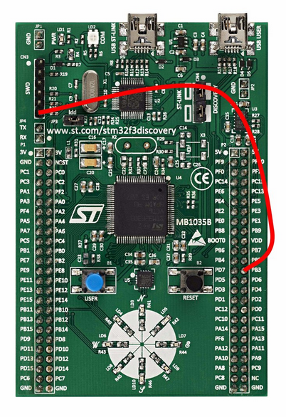
OR
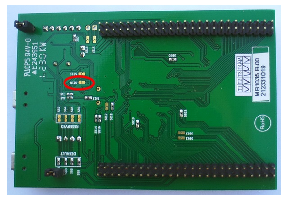
- Close the solder bridge (jumper) SB10 at the botom of the board by soldering the two pads together. This is a more permanent option, but can be reversed by carefully de-soldering the two pads and making sure with a multi-meter that they are indeed seperated.
*** IMPORTANT NOTICE ***
Please note that PB3 can now not be used as a normal GPIO pin, until the above changes are reversed.
Configuring a Keil project
Assuming that you have an already working project which is correctly set up for Flash programming and debugging, do the following to add the SWV capability (you can use the example source files at the top of this page):
- Open the project in Keil MDK (uVision)
- Right-click on the project name in the Project window and select Options for target ...
- In the Debug tab, select Settings
- In the Trace tab, make the following selections:
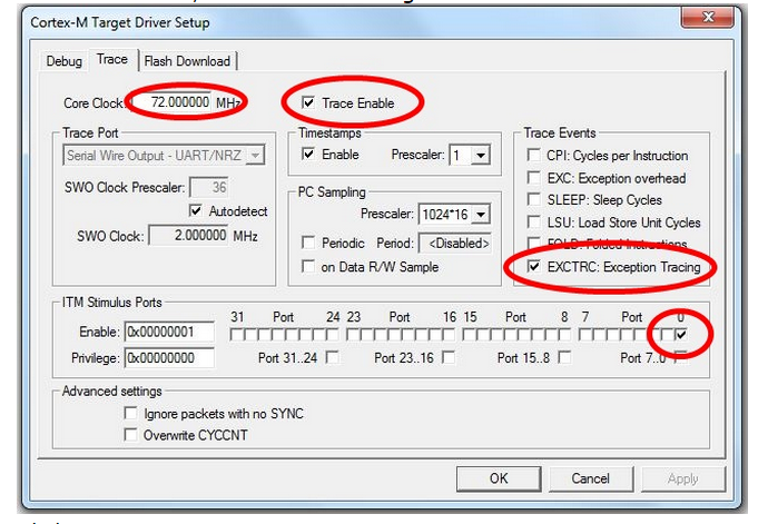
- Click OK
- Close the Options for Target dialog
- Compile and Flash Download (program)/Debug as usual.
Add code
The standard printf statement makes use of the fputc function. We need to retarget the fputc function to use the Trace on ITM Stimulus Port 0. To do this, simply add the following code to your programs that uses the SWV:
int fputc(int ch, FILE *f)
{
return(ITM_SendChar(ch));
}
The fputc function could actually be retargetted to print to the SWV and to the USART (or even an LCD) at the same time, e.g:
int fputc(int ch, FILE *f)
{
/* the USART */
UART4->TDR = (ch & (uint16_t)0x01FF);
while ((UART4->ISR & USART_FLAG_TXE) == (uint16_t) RESET);
/* the SWV */
return(ITM_SendChar(ch));
}
Using the Serial Wire Viewer (SWV)
Once all the previous topics were done, do the following to use the SWV:
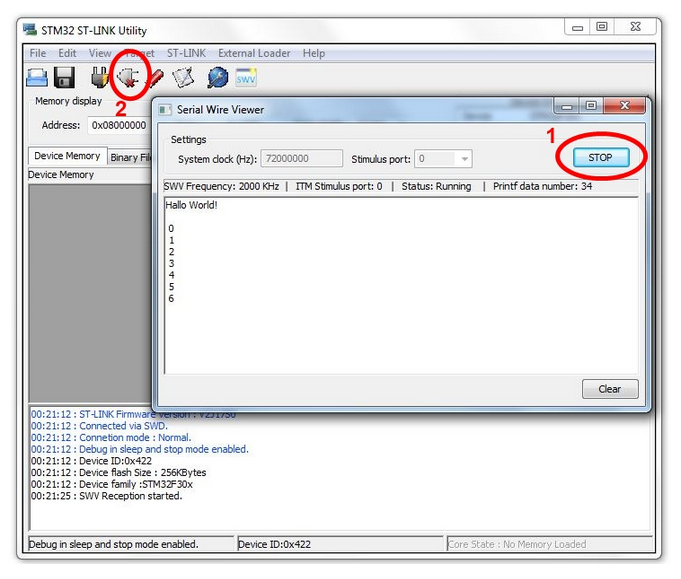
- Open the STM32 ST-Link Utility
- Select ST-LINK → Printf via SWO viewer
- Set the System clock to 72000000
- Set the Stimulus port to 0
- Click Start
The SWV is now ready for receiving characters and values from the printf statements in the source code. It has now grabbed the handle and interface to the ST-Link/V2 programmer and Flash Downloading and Debuggin in uVision will now not be possible. To reprogram changes or new source code to the STM32F3-Discovery board, you will have to:
- Click STOP in the SWV window
- Click the Disconnect button
The handle and interface to the ST-Link/V2 programmer is now released and can be used in Keil uVision again to program the device as usual.
Clicking Start in the SWV window will now reset the board and start the serial connection again.
/*#############################################################

 File Name       : ex1_SWOViewer_HelloWorld.c

 Author          : Grant Phillips

 Date Modified   : 13/05/2014

 Compiler        : Keil ARM-MDK (uVision V4.70.0.0)

 Tested On       : STM32F3-Discovery

 Description     : Example program that uses Trace Events to

 write "Hello World!" via the ST-Link programmer

 to the ST-Link Utility's SWO Viewer and then

 display a count from 0 to 255 repeatedly. The

 count value is also written to the 8 USER LEDs.

 Visit the following link for more information

 regarding the SWO Viewer:

 http://controlsoft.nmmu.ac.za/STM32F3-Discovery

 -Board/Example-programs/SWO-Viewer

 Requirements    : * STM32F3-Discovery Board

 Circuit         : * A wire link between PB3 and pin6 of the SWD

 connector (CN3)

 OR

 solder the solder bridge SB10 closed underneath

 the board

 Note that PB3 will now not be available as a

 normal GPIO pin.

 See the STM32F3-Discovery User Manual (UM1570) for the block

 diagram of the STM32F303VCT6 processor (p13), a summary of

 the GPIO connections (p21-29) and the schematic diagram (p31-34)

 ##############################################################*/

/* #includes -------------------------------------------------*/

#include "main.h"

//main library to include for device drivers, peripheral drivers, etc.

/* #defines --------------------------------------------------*/

/* #function prototypes --------------------------------------*/

void InitLEDs( void ); //prototype for the user function to initialize the USER LEDs

/* #global variables -----------------------------------------*/

// Unused global variables that have to be included to ensure correct compiling */

// ###### DO NOT CHANGE ######

// ===============================================================================

__IO uint32_t TimingDelay = ;                    //used with the Delay function

__IO uint8_t DataReady = ;

__IO uint32_t USBConnectTimeOut = ;

__IO uint32_t UserButtonPressed = ;

__IO uint8_t PrevXferComplete = ;

// ===============================================================================

int main( void )

{

  uint8_t count = ;    //8-bit integer variable to hold the count value (0-255)

  RCC_ClocksTypeDef RCC_Clocks; //structure used for setting up the SysTick Interrupt

  /* Set the SysTick Interrupt to occur every 1ms) */

  RCC_GetClocksFreq( &RCC_Clocks );

  if ( SysTick_Config( RCC_Clocks.HCLK_Frequency /  ) )

    while (  )

      ; //will end up in this infinite loop if there was an error with Systick_Config

  InitLEDs( ); //initialize the USER LEDs for this application

  //print a message to the SWO Viewer (make sure the fputc function is

  //retargeted as shown by the fputc function just after main()

  printf( "Hallo World!\n" );

  /* Main program loop */

  while (  )

  {

    printf( "\n%2X", count );       //print a newline and integer value (in HEX)

    GPIO_Write( GPIOE, count <<  );

    //shift the value 8 spaces to the left,

    //because we are writing it to the high byte (PE15 - PE8)

    count = count + ;

    Delay(  );

  }

}

/*

 Retarget the C library printf function to the SWO Viewer.

 Overwrites int fputc(int ch, FILE *f) function used by printf.

 */

int fputc( int ch, FILE *f )

{

  return ( ITM_SendChar( ch ) );

}

void InitLEDs( void )

{

  GPIO_InitTypeDef GPIO_InitStructure; //structure used for setting up a GPIO port

  /* GPIOE Periph clock enable */

  RCC_AHBPeriphClockCmd( RCC_AHBPeriph_GPIOE, ENABLE );

  /* Configure PE15 - PE8 in output pushpull mode */

  GPIO_InitStructure.GPIO_Pin = GPIO_Pin_15 | GPIO_Pin_14 | GPIO_Pin_13

    | GPIO_Pin_12 | GPIO_Pin_11 | GPIO_Pin_10 | GPIO_Pin_9 | GPIO_Pin_8;

  //which pins to setup, seperated by |

  GPIO_InitStructure.GPIO_Mode = GPIO_Mode_OUT;

  GPIO_InitStructure.GPIO_OType = GPIO_OType_PP;

  GPIO_InitStructure.GPIO_Speed = GPIO_Speed_50MHz;

  GPIO_InitStructure.GPIO_PuPd = GPIO_PuPd_NOPULL;

  GPIO_Init( GPIOE, &GPIO_InitStructure );

}

// -------------------------------------------------------------------------------

// Function to insert a timing delay of nTime

// ###### DO NOT CHANGE ######

void Delay(__IO uint32_t nTime)

{

  TimingDelay = nTime;

  while(TimingDelay != );

}

// Function to Decrement the TimingDelay variable.

// ###### DO NOT CHANGE ######

void TimingDelay_Decrement( void )

{

  if ( TimingDelay != 0x00 )

  {

    TimingDelay--;

  }

}

// Unused functions that have to be included to ensure correct compiling

// ###### DO NOT CHANGE ######

// =======================================================================

uint32_t L3GD20_TIMEOUT_UserCallback( void )

{

  return ;

}

uint32_t LSM303DLHC_TIMEOUT_UserCallback( void )

{

  return ;

}

// =======================================================================
Serial Wire Viewer (SWV)的更多相关文章
- Serial Wire Debug (SWD) Interface -- PSoc5
PSoC 5 supports programming through the serial wire debug (SWD) interface. There are two signals in ...
- SW-DP (Serial Wire Debug Port) Analyzer plugin for the Saleae Logic
SW-DP (Serial Wire Debug Port) Analyzer plugin for the Saleae Logic The SW-DP protocol is described ...
- Programming Internal Flash Over the Serial Wire Debug <SWD> Interface -- EFM32
1 Debug Interface Overview 1.1 Serial Wire Debug Serial Wire Debug (SWD) is a two-wire protocol for ...
- Serial Wire Debugging the STM32 via the Bus Pirate
Serial Wire Debugging the STM32 via the Bus Pirate 2 October 2010 Step 1 - The Bus Pirate Step 2 - D ...
- Implementation of Serial Wire JTAG flash programming in ARM Cortex M3 Processors
Implementation of Serial Wire JTAG flash programming in ARM Cortex M3 Processors The goal of the pro ...
- Introduction to Cortex Serial Wire Debugging
Serial Wire Debug (SWD) provides a debug port for severely pin limited packages, often the case for ...
- windows下STM32开发环境的搭建
一.概述 1.说明 笔者已经写了一篇Linux下STM32开发环境的搭建 ,这两篇文章的最区别在于开发环境所处的系统平台不一样,而其实这个区别对于开发环境的搭建其实影响不大,制作局部上的操作上发生了改 ...
- Keil debugging techniques and alternative printf (SWO function)
One of the basic needs of the embedded software development through the terminal to output debugging ...
- CoreSight™ Technology
ARM Cortex-M processor-based devices use the ARM CoreSight technology which introduces powerful new ...
随机推荐
- Jenkins mac pkg安装 后默认配置文件/启动路径
自启动文件路径 /Library/LaunchDaemons/org.jenkins-ci.plist jenkins.war 执行文件路径 /Applications/Jenkins/jenkins ...
- HDU 4509 湫湫系列故事——减肥记II (简单模拟)
题意:一天一共有1440分钟,主人公每天有n件事要做,给出这n件事开始跟结束的时间,然后让你求出,空闲的时间的总分钟数是多少. 解题报告:简单模拟,只要开个一维数组标记那个每个分钟是否是有事的就可以了 ...
- python的__get__、__set__、__delete__(1)
内容: 描述符引导 摘要 定义和介绍 描述符协议 调用描述符 样例 Properties 函数和 ...
- CSS absolute与relative不得不说的故事
写在开篇: absolute说:“relative,我这辈子都不想看见你!” 为什么呢?它们明明那么相亲相爱,形影不离,这之中到底发生了什么不为人知的故事,竟然让absolute如此讨厌relativ ...
- MYSQL 的 MASTER到MASTER的主主循环同步
MYSQL 的 MASTER到MASTER的主主循环同步 刚刚抽空做了一下MYSQL的主主同步.把步骤写下来,至于会出现的什么问题,以后随时更新.这里我同步的数据库是TEST1.环境描述. 主 ...
- Shell脚本中实现切换用户并执行命令操作【转】
第一种方法 cat test.sh #!/bin/bashsu - test <<EOFpwd;exit;EOF 执行结果图: 第二种方法 当然也可以用下面的命令来执行 复制代码代码如下: ...
- PGP工作原理及其安全体制
现代信息社会里,当电子邮件广受欢迎的同时,其安全性问题也很突出.实际上,电子邮件的传递过程是邮件在网络上反复复制的过程,其网络传输路径不确定,很容易遭到不明身份者的窃取.篡改.冒用甚至恶意破坏,给收发 ...
- redis配置文件redis.conf翻译、解释以及常用注意事项(持续更新中...)
# Redis configuration file example. #Redis 配置文件的示例 #如何利用配置文件启动Redis # Note that in order to read the ...
- 全键盘操作Windows
计算机机用户在使用计算机的时候,是用键盘多一点?还是用鼠标多一点?如果是专业打字员,应该会说他使用键盘多一点,除此之外,多数人都会告诉你,他已经离不开鼠标了,没有鼠标,就不会操作电脑. 如果某一天 ...
- python3.6连接oracle数据库
下载cx_Oracle模块模块: https://pypi.python.org/pypi/cx_Oracle/5.2.1#downloads 这里下载的是源码进行安装 [root@oracle or ...