DIY FSK RFID Reader
This page describes the construction of an RFID reader using only an Arduino (Nano 3.0 was tested, but others may work), a hand-wound wire coil, and some assorted low cost common components.
Credits
The hardware and software designs for this project are based in part on the ideas, code and schematics posted by Micah Dowty here and Asher Glick here.
Background
RFID readers are devices sold by companies such as Parallax to read RFID tags with embedded identification circuits (we focus here on passive tags, activated by the reader's transmitted RF energy). The design presented here shows how to wind a simple wire loop by hand (or create an equivalent printed circuit spiral version), connect it to an Arduino (or its chip), add a few low cost common components and create your own RFID reader. To make it more interesting (i.e. challenging), we will focus on the FSK class of RFID tags, which are fairly common among the 125kHz devices, but for some reason are not supported by the Parallax kits.
Micah Dowty has shown a design for an FSK/ASK RFID reader built around a Parallax Propeller device. His code, which is in assembly language, implements an ingenious (but complex) algorithm to create a dynamically variable analog bias voltage, which is used to pull the weak RFID signal into range, so it can be discriminated into binary signals by the Propeller's digital input circuitry. He also dynamically tweaks the transmit/receive RF frequency to keep the antenna's tank circuit in peak resonance for optimal signal to noise. There are three problems with his approach: first, the passive detection circuit lacks amplification, which makes it very sensitive to noise and therefore raises reliability issues. Second, the design is based on the Propeller chip, and if you are a fan of the Arduino and/or associated Atmel AVR chips, it leaves you out. And third, the dynamic slewing of frequencies and bias voltage is overly complicated, making it hard to debug. His general concept is attractive, however: use a microcontroller chip and wind your own wire loop to create, with some simple components and appropriate code, a complete DIY RFID reader.
Asher Glick has presented a solution for reading and decoding FSK RFID tags using the Arduino/AVR family (which he calls AVRFID), which is good except it apparently requires obtaining and modifying an existing Parallax RFID reader device (which natively only supports ASK).
Our goal here is to present a simple solution for reading FSK tags which addresses the above shortcomings: make it robust and reliable for real-world noise environments, base it on the Arduino, and build the RFID reader ourselves using a few simple low-cost parts, rather than buying and/or modifying one.
Circuit
Arduino DIY FSK-RFID circuit diagram:
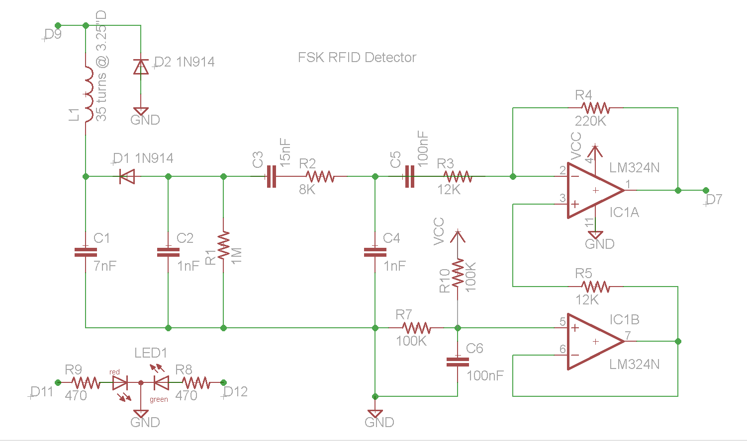
The circuit diagram above was derived from the "World's Simplest RFID Reader" design posted by Micah Dowty. Based on the Parallax Propeller, Micah's approach was to use passive components only, without amplification, in order to achieve the ultimate in simplicity. The lack of amplification, however, results in a weak signal, potentially less than 2V PTP. This signal is then biased by an analog level produced by the Propeller, to try to maintain the signal's DC level near the discrimination point of the Propeller's binary-digital input circuitry. His code attempts to dynamically calculate that optimal midpoint level, and feed it into the circuit using a filtered PWM DAC output. Since the signal is weak, it can be distorted by interference and noise, which results in reduced reliability. The circuit presented here includes (as Micah suggests in his documentation) one active component: a common low-cost LM234 quad-opamp IC (or equivalent). This addition provides several significant advantages, at a negligible cost. First, the signal is amplified (using one of the four opamps on the IC package) to a more noise-immune level (of 2-3 volts PTP). Second, the DC level of the signal is maintained at exactly Vcc/2 using another opamp on the IC, which eliminates the need for the DC propping code in the Arduino. Third, having the signal amplifier in place allows another low-pass RC filter stage (another capacitor and resistor), which makes the final discriminated digital signal cleaner and more reliable. The end result is a more robust detected signal with improved noise immunity.
As a quick review of the circuit, the loop is made of a toroidally-wound #22-30 magnet wire (we used an empty roll of Scotch 3.25" I.D. packing tape as former), and can be remoted from the circuit if needed, via coaxial cable. The inductor L1 and capacitance C1 should be matched to resonate at around 125 kHz. When driven at its resonant frequency by the Arduino's 0-5 volt square wave signal, the center point of the resonator (which connects to D1's cathode) will have a fairly pure voltage sine wave, of about 30V PTP. When coupled to an RFID tag, the pure sine wave RF will fluctuate visibly as the tag opens and closes its own loop antenna to repeatedly transmit its code. This modulation is then detected from the RF envelope by D1, C2 and R1, which produce a negative bias voltage with the small detected coded signal, e.g. about 11 RF cycles per coded cycle. The coded cycles are of two different wave lengths (or frequencies), which represent streams of logic ones and zeros, and they need to arrive at the Arduino chip as binary levels which can be timed reasonably accurately so as to reliably tell the difference between the two distinct frequencies.
The relatively large capacitor C3 decouples the negative bias voltage from the signal, and is followed by a low-pass RC filter stage (R2 and C4) which attenuates some of the residual RF spikes from the lower frequency coded RFID signal. Capacitor C5 decouples the resulting signal and presents it to the amplification stage, implemented by the LM324 opamp, IC1. The latter amplifies the weak signal from about .15V to about 3V PTP (depending of the ratio of R4 to R3), and places it on top of a Vcc/2 bias voltage, about 2.5V in the arduino's case. This signal is then fed into one of the digital input ports on the Arduino (which also includes some helpful hysteresis), and is discriminated by the internal comparator into a square wave of ones and zeroes.
Software
The Arduino sketch, derived from the code posted by Asher Glick, uses a single timer channel in the Arduino (using the Timer1 library) for both RF signal generation as well as timing clock to count the width of each input signal wave. There are two distinct cycle lengths in the detected input signal, "long" and "short", corresponding to logical ones and zeroes, respectively. A binary stream of stretches of repeated ones and zeroes is assembled, and then decimated into the original coded bits on the RFID tag, after decoding the Manchester encoding.
Here is the actual code:
/*  Arduino program for DIY FSK RFID Reader

 *  See description and circuit diagram at http://playground.arduino.cc/Main/DIYRFIDReader

 *  Tested on Arduino Nano and several FSK RFID tags

 *  Hardware/Software design is based on and derived from:

 *  Arduino/Timer1 library example

 *  June 2008 | jesse dot tane at gmail dot com

 *  AsherGlick: / AVRFID https://github.com/AsherGlick/AVRFID

 *  Micah Dowty:

 *  http://forums.parallax.com/showthread.php?105889-World-s-simplest-RFID-reader

 *

 *  Copyright (C) 2011 by edude/Arduino Forum

 This program is free software: you can redistribute it and/or modify

 it under the terms of the GNU General Public License as published by

 the Free Software Foundation, either version 3 of the License, or

 (at your option) any later version.

 This program is distributed in the hope that it will be useful,

 but WITHOUT ANY WARRANTY; without even the implied warranty of

 MERCHANTABILITY or FITNESS FOR A PARTICULAR PURPOSE.  See the

 GNU General Public License for more details.

 You should have received a copy of the GNU General Public License

 along with this program.  If not, see <http://www.gnu.org/licenses/>.

 */

#include "TimerOne.h"

int ledPin = 13; // LED connected to digital pin 13

int inPin = 7;   // sensing digital pin 7

int val;

int bitlenctr = 0;

int curState = 0;

#define maxBuf 1000 //reduce to 100 or so for debugging

#define debug  0

char raw[maxBuf];

int index = 0;

int bufnum = 0;

#define   redLED 12

#define   grnLED 11

void setup()

{

  Serial.begin(9600);

  Timer1.initialize(7);  // initialize timer1, and set the frequency; this drives both the LC tank as well as the pulse timing clock

  // note: modify this as needed to achieve resonance and good match with the desired tags

  // the argument value is in microseconds per RF cycle, so 8us will yield RF of 125kHz, 7us --> 143kHz, etc.

  Timer1.pwm(9, 512);           // setup pwm on pin 9, 50% duty cycle

  Timer1.attachInterrupt(callback);  // attaches callback() as a timer overflow interrupt, once per RF cycle

  pinMode(ledPin, OUTPUT);      // sets the digital pin 13 as output for scope monitoring

  pinMode(inPin, INPUT);      // sets the digital pin 7 as input to sense receiver input signal

  pinMode(grnLED, OUTPUT);

  pinMode(redLED, OUTPUT);

  digitalWrite(grnLED, 0);

  digitalWrite(redLED, 1);

}

void callback()

{

  val = digitalRead(inPin);

  digitalWrite(ledPin, val); // for monitoring

  bitlenctr++;

  if(val != curState) {

    // got a transition

    curState = val;

    if(val == 1) {

      // got a start of cycle (low to high transition)

      if(index < maxBuf) {

        raw[index++] = bitlenctr;

      }

      bitlenctr = 1;

    }

  }

}

void loop()

{

  if(index >= maxBuf) {

    Serial.print("got buf num: ");

    Serial.println(bufnum);

    if(debug) {

      for(int i = 0; i < maxBuf;

      i++) {

          Serial.print((int)raw[i]);

        Serial.print("/");

      }

      Serial.println("///raw data");

      delay(2000);

    }

    // analyze this buffer

    // first convert pulse durations into raw bits

    int tot1 = 0;

    int tot0 = 0;

    int tote = 0;

    int totp = 0;

    raw[0] = 0;

    for(int i = 1; i < maxBuf; i++) {

      int v = raw[i];

      if(v == 4) {

        raw[i] = 0;

        tot0++;

      }

      else if(v == 5) {

        raw[i] = raw[i - 1];

        totp++;

      }

      else if(v == 6 || v == 7) {

        raw[i] = 1;

        tot1++;

      }

      else {

        raw[i] = 101; // error code

        tote++;

      }

    }

    // next, search for a "start tag" of 15 high bits in a row

    int samecnt = 0;

    int start = -1;

    int lastv = 0;

    for(int i = 0; i < maxBuf; i++) {

      if(raw[i] == lastv) {

        // inside one same bit pattern, keep scanning

        samecnt++;

      }

      else {

        // got new bit pattern

        if(samecnt >= 15 && lastv == 1) {

          // got a start tag prefix, record index and exit

          start = i;

          break;

        }

        // either group of 0s, or fewer than 15 1s, so not a valid tag, keep scanning

        samecnt = 1;

        lastv = raw[i];

      }

    }

    // if a valid prefix tag was found, process the buffer

    if(start > 0 && start < (maxBuf - 5*90)) { //adjust to allow room for full dataset past start point

      process_buf(start);

    }

    else {

      Serial.println("no valid data found in buffer");

    }

    if(debug) {

      for(int i = 0; i < maxBuf;

        i++) {

          Serial.print((int)raw[i]);

        Serial.print("/");

      }

      Serial.print("///\nbuffer stats: zeroes:");

      Serial.print(tot0);

      Serial.print("/ones:");

      Serial.print(tot1);

      Serial.print("/prevs:");

      Serial.print(totp);

      Serial.print("/errs:");

      Serial.println(tote);

      delay(1000);

    }

    // start new buffer, reset all parameters

    bufnum++;

    curState = 0;

    index = 0;

  }

  else {

    delay(5);

  }

}

// process an input buffer with a valid start tag

// start argument is index to first 0 bit past prefix tag of 15+ ones

void process_buf(int start) {

  // first convert multi bit codes (11111100000...) into manchester bit codes

  int lastv = 0;

  int samecnt = 0;

  char manch[91];

  char final[45];

  int manchindex = 0;

  Serial.println("got a valid prefix, processing data buffer...");

  for(int i = start + 1; i < maxBuf && manchindex < 90; i++) {

    if(raw[i] == lastv) {

      samecnt++;

    }

    else {

      // got a new bit value, process the last group

      if(samecnt >= 3 && samecnt <= 8) {

        manch[manchindex++] = lastv;

      }

      else if(samecnt >= 9 && samecnt <= 14) {

        // assume a double bit, so record as two separate bits

        manch[manchindex++] = lastv;

        manch[manchindex++] = lastv;

      }

      else if(samecnt >= 15 && lastv == 0) {

        Serial.println("got end tag");

        // got an end tag, exit

        break;

      }

      else {

        // last bit group was either too long or too short

        Serial.print("****got bad bit pattern in buffer, count: ");

        Serial.print(samecnt);

        Serial.print(", value: ");

        Serial.println(lastv);

        err_flash(3);

        return;

      }

      samecnt = 1;

      lastv = raw[i];

    } //new bit pattern

  }

  Serial.println("converting manchester code to binary...");

  // got manchester version, convert to final bits

  for(int i = 0, findex = 0; i < 90; i += 2, findex++) {

    if(manch[i] == 1 && manch[i+1] == 0) {

      final[findex] = 1;

    }

    else if(manch[i] == 0 && manch[i+1] == 1) {

      final[findex] = 0;

    }

    else {

      // invalid manchester code, exit

      Serial.println("****got invalid manchester code");

      err_flash(3);

      return;

    }

  }

  // convert bits 28 thru 28+16 into a 16 bit integer

  int code = 0;

  int par = 0;

  for(int i = 28, k = 15; i < 28+16; i++, k--) {

    code |= (int)final[i] << k;

  }

  int paritybit = final[28+16];

  for(int i = 0; i < 45; i++) {

    par ^= final[i];

  }

  if(par) {

    Serial.print("got valid code: ");

    Serial.println((unsigned int)code);

    // do something here with the detected code...

    //

    //

    digitalWrite(redLED, 0);

    digitalWrite(grnLED, 1);

    delay(2000);

    digitalWrite(grnLED, 0);

    digitalWrite(redLED, 1);

  }

  else {

    Serial.println("****parity error for retrieved code");

    err_flash(3);

  }

}

// flash red for duration seconds

void err_flash(int duration) {

  return;

  for(int i = 0; i < duration*10; i++) {

    digitalWrite(redLED, 0);

    delay(50);

    digitalWrite(redLED, 1);

    delay(50);

  }

}
Status
The device and transceiver antenna have been built and tested on multiple FSK RFID tags of various kinds, in breadboard and soldered perfboard versions, connected to remote and local probes. When the probe is properly tuned, the device can reliably detect FSK RFID tags within a range of 0 to at least 2 inches from the coil, although it may be possible that this can be extended with larger coil sizes and/or other optimizations. The circuit has also been simulated on Spice, as described below.
Spice simulation
LTspiceIV simulated waveforms of FSK RFID reader plus transponder tag:
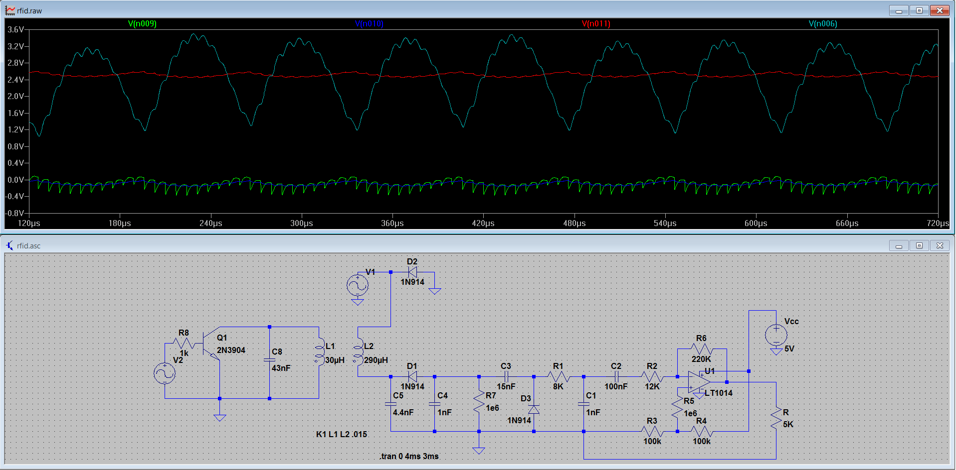
As seen in the LTspiceIV screenshot above, the circuit (with a passive virtual ground reference - see note below) was simulated on a computer, and the results confirmed the essential design, closely replicating the waveforms actually seen on the oscilloscope. The RFID transponder tag was simulated as a coupled transformer winding with a resonantly tuned capacitor, shunted to ground by a square-wave signal. The RFID tag's ground is connected to the main circuit's ground for simulation purposes. The inductive coupling between the two "transformer windings" is a variable which can be changed in LTspice, and was varied for testing between 1 and 0.01 (0.015 is shown in the waveforms above), equivalent to having the RFID tag positioned at different distances from the reader coil.
Notes
The Vcc/2 virtual ground voltage for IC1's non-inverting input can also be taken directly from the midpoint of the 100K voltage divider resistors, bypassing the second opamp. In such a case, the divider's midpoint should be connected to pin3 of IC1 via a 1M resistor.
References
- LM324 Quad Operational Amplifier datasheet
- TI application note for single supply opamp use
- World's simplest RFID reader
- Arduino Nano description and specs
- App note for EM4095 IC (this IC officially supports only ASK mode, but much of the analysis is also relevant for FSK)
- Generic info about capacitors and bypass/decoupling
- Generic info about filter design
原帖连接:http://playground.arduino.cc/Main/DIYRFIDReader
DIY FSK RFID Reader的更多相关文章
- RFID Reader 线路图收集
This 125 kHz RFID reader http://www.serasidis.gr/circuits/RFID_reader/125kHz_RFID_reader.htm http:// ...
- RFIDler - An open source Software Defined RFID Reader/Writer/Emulator
https://www.kickstarter.com/projects/1708444109/rfidler-a-software-defined-rfid-reader-writer-emul h ...
- 极客DIY:RFID飞贼打造一款远距离渗透利器
本文使用最新的渗透工具RFID飞贼(Tastic RFID Thief)和RFID感应破解技术来获取一些拥有安防的建筑物的访问权限. Tastic RFID Thief是一个无声远距离RFID读卡器, ...
- RFID Reader ICs
http://www.advanide.com/readeric.htm Low Frequency Reader ICs Manufacturer Product Frequency ISO Com ...
- RFID 读写器 Reader Writer Cloner
RFID读写器的工作原理 RFID的数据采集以读写器为主导,RFID读写器是一种通过无线通信,实现对标签识别和内存数据的读出和写入操作的装置. 读写器又称为阅读器或读头(Reader).查询器(Int ...
- RFID 仿真/模拟/监控/拦截/检测/嗅探器
Sound card based RFID sniffer/emulator (Too tired after recon.cx to do draw the schematics better th ...
- RFID Exploration and Spoofer a bipolar transistor, a pair of FETs, and a rectifying full-bridge followed by a loading FET
RFID Exploration Louis Yi, Mary Ruthven, Kevin O'Toole, & Jay Patterson What did you do? We made ...
- Radio Basics for RFID
Radio Basics for RFID The following is excerpted from Chapter 3: Radio Basics for UHF RFID from the ...
- RFID 基础/分类/编码/调制/传输
不同频段的RFID产品会有不同的特性,本文详细介绍了无源的感应器在不同工作频率产品的特性以及主要的应用. 目前定义RFID产品的工作频率有低频.高频和甚高频的频率范围内的符合不同标准的不同的产品,而且 ...
随机推荐
- [转]为何需要调用“super viewDidLoad
转载地址:http://liwpk.blog.163.com/blog/static/36326170201165104413314/ - (void)didReceiveMemoryWarnin ...
- Android中Bitmap和Drawable
一.相关概念 1.Drawable就是一个可画的对象,其可能是一张位图(BitmapDrawable),也可能是一个图形(ShapeDrawable),还有可能是一个图层(LayerDrawable) ...
- 自建数据源(RSO2)、及数据源增强
声明:原创作品,转载时请注明文章来自SAP师太技术博客( 博/客/园www.cnblogs.com):www.cnblogs.com/jiangzhengjun,并以超链接形式标明文章原始出处,否则将 ...
- iOS- iPhone App 如何运营?
在质量过硬的情况下,如何运营才能使APP冲上app store的推荐?如何获得公众认可?获得下载量? 睡前简单分享一下最近从书中.互联网中浏览到的一些信息,和自己的一点理解. 首先这个问题很大.就抛砖 ...
- HTML表格与列表
HTML表格 表格其实就是很多的小单元格,而这些小单元格很有次序的排列着,它们有很多行,很多列.这些很多行列组成的东西,就叫表格,表格是<table>标签来定义的.而<table&g ...
- iOS - Mac Apache WebDav 服务器配置
前言 Apache 服务器: Web 服务器,可以支持各种脚本(PHP)的执行,目前世界上使用最为广泛的一种 Web 服务器 WebDav 服务器: 基于 http 协议的 "文件" ...
- FTPS链接服务器
一.首先登录ftp服务器:命令行 lftp user@ip 上传:put 下载: get 二. 关于FTP传输模式与传输的方式 众所周知,FTP传输有两种工作模式,Active Mode和Pass ...
- Head First 设计模式 --8 模板方法模式 别找我,我会找你
模板方法模式:在一个方法中定义一个算法的骨架,而将一些步骤延迟到子类中.模板方法使得子类可以在不改变算法结构的情况下,重新定义算法中的某些步骤.设计原则:1.封装变化2.多用组合少用集成3.针对接口变 ...
- node.js基础 1之 URL网址解析的好帮手
URL和URI的区别: URL是统一资源定位符 URI是统一资源标识符 URL是URI的子集(URL一定是URI,但URI不一定是URL) node中的URL中的url.parse protocol: ...
- 课时8—弹窗modal
首先弹窗的实现效果如下: 主要实现的代码如下: CSS: .header,.footer,.wrap-page{ position:absolute; left:; right:; backgroun ...