hbot固件配置
又入了一台打印机,171到手,本来之前有更好的,无奈别人下手太快,只剩这台了。
175x135x180的样子。
创客的板,还带16g的闪迪内存卡,看到那会儿感觉赚大了!
拿到的时候不少螺丝松的,有的打印件也裂口了,拧紧螺丝,调平后打了打感觉操作很多不习惯,
连上电脑看固件原来是marlin1.0的!上github下载了1.19固件,网上似乎没有找到关于hbot的配置贴,
反正以前琢磨过不少次,直接上configuration.h 凭借经验改了改,基本能用了。之后有待调试。

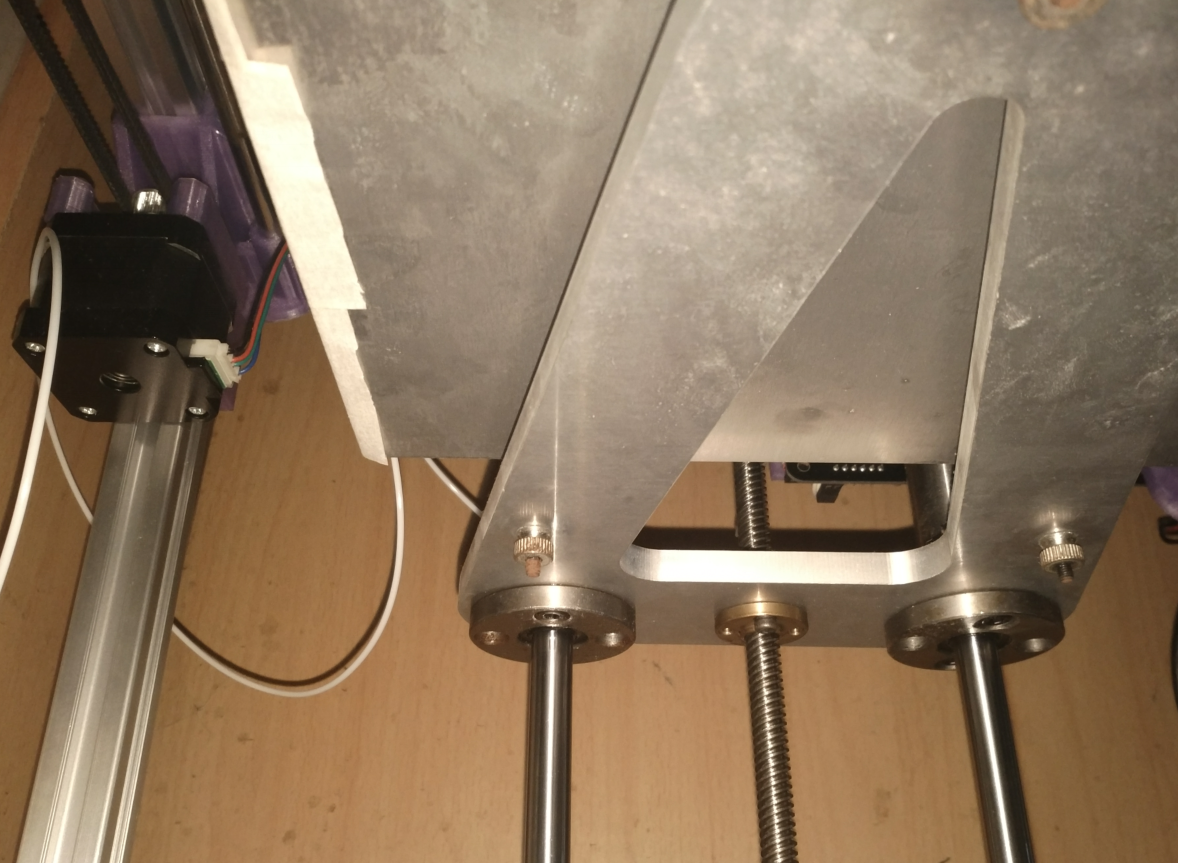
这个平台用料很足,3点很方便调平,拧几下螺丝就解决了
/**
* Marlin 3D Printer Firmware
* Copyright (C) 2016 MarlinFirmware [https://github.com/MarlinFirmware/Marlin]
*
* Based on Sprinter and grbl.
* Copyright (C) 2011 Camiel Gubbels / Erik van der Zalm
*
* This program is free software: you can redistribute it and/or modify
* it under the terms of the GNU General Public License as published by
* the Free Software Foundation, either version 3 of the License, or
* (at your option) any later version.
*
* This program is distributed in the hope that it will be useful,
* but WITHOUT ANY WARRANTY; without even the implied warranty of
* MERCHANTABILITY or FITNESS FOR A PARTICULAR PURPOSE. See the
* GNU General Public License for more details.
*
* You should have received a copy of the GNU General Public License
* along with this program. If not, see <http://www.gnu.org/licenses/>.
*
*/ /**
* Configuration.h
*
* Basic settings such as:
*
* - Type of electronics
* - Type of temperature sensor
* - Printer geometry
* - Endstop configuration
* - LCD controller
* - Extra features
*
* Advanced settings can be found in Configuration_adv.h
*
*/
#ifndef CONFIGURATION_H
#define CONFIGURATION_H
#define CONFIGURATION_H_VERSION 010109 //===========================================================================
//============================= Getting Started =============================
//=========================================================================== /**
* Here are some standard links for getting your machine calibrated:
*
* http://reprap.org/wiki/Calibration
* http://youtu.be/wAL9d7FgInk
* http://calculator.josefprusa.cz
* http://reprap.org/wiki/Triffid_Hunter%27s_Calibration_Guide
* http://www.thingiverse.com/thing:5573
* https://sites.google.com/site/repraplogphase/calibration-of-your-reprap
* http://www.thingiverse.com/thing:298812
*/ //===========================================================================
//============================= DELTA Printer ===============================
//===========================================================================
// For a Delta printer start with one of the configuration files in the
// example_configurations/delta directory and customize for your machine.
// //===========================================================================
//============================= SCARA Printer ===============================
//===========================================================================
// For a SCARA printer start with the configuration files in
// example_configurations/SCARA and customize for your machine.
// // @section info // User-specified version info of this build to display in [Pronterface, etc] terminal window during
// startup. Implementation of an idea by Prof Braino to inform user that any changes made to this
// build by the user have been successfully uploaded into firmware.
#define STRING_CONFIG_H_AUTHOR "(none, default config)" // Who made the changes.
#define SHOW_BOOTSCREEN
#define STRING_SPLASH_LINE1 SHORT_BUILD_VERSION // will be shown during bootup in line 1
#define STRING_SPLASH_LINE2 WEBSITE_URL // will be shown during bootup in line 2 /**
* *** VENDORS PLEASE READ ***
*
* Marlin allows you to add a custom boot image for Graphical LCDs.
* With this option Marlin will first show your custom screen followed
* by the standard Marlin logo with version number and web URL.
*
* We encourage you to take advantage of this new feature and we also
* respectfully request that you retain the unmodified Marlin boot screen.
*/ // Enable to show the bitmap in Marlin/_Bootscreen.h on startup.
//#define SHOW_CUSTOM_BOOTSCREEN // Enable to show the bitmap in Marlin/_Statusscreen.h on the status screen.
//#define CUSTOM_STATUS_SCREEN_IMAGE // @section machine /**
* Select the serial port on the board to use for communication with the host.
* This allows the connection of wireless adapters (for instance) to non-default port pins.
* Serial port 0 is always used by the Arduino bootloader regardless of this setting.
*
* :[0, 1, 2, 3, 4, 5, 6, 7]
*/
#define SERIAL_PORT 0 /**
* This setting determines the communication speed of the printer.
*
* 250000 works in most cases, but you might try a lower speed if
* you commonly experience drop-outs during host printing.
* You may try up to 1000000 to speed up SD file transfer.
*
* :[2400, 9600, 19200, 38400, 57600, 115200, 250000, 500000, 1000000]
*/
#define BAUDRATE 250000 // Enable the Bluetooth serial interface on AT90USB devices
//#define BLUETOOTH // The following define selects which electronics board you have.
// Please choose the name from boards.h that matches your setup
#ifndef MOTHERBOARD
#define MOTHERBOARD BOARD_MKS_BASE //******changeded
#endif // Optional custom name for your RepStrap or other custom machine
// Displayed in the LCD "Ready" message
//#define CUSTOM_MACHINE_NAME "3D Printer" // Define this to set a unique identifier for this printer, (Used by some programs to differentiate between machines)
// You can use an online service to generate a random UUID. (eg http://www.uuidgenerator.net/version4)
//#define MACHINE_UUID "00000000-0000-0000-0000-000000000000" // @section extruder // This defines the number of extruders
// :[1, 2, 3, 4, 5]
#define EXTRUDERS 1 // Generally expected filament diameter (1.75, 2.85, 3.0, ...). Used for Volumetric, Filament Width Sensor, etc.
#define DEFAULT_NOMINAL_FILAMENT_DIA 1.75 //*****changeded // For Cyclops or any "multi-extruder" that shares a single nozzle.
//#define SINGLENOZZLE /**
* Pr暖拧a MK2 Single Nozzle Multi-Material Multiplexer, and variants.
*
* This device allows one stepper driver on a control board to drive
* two to eight stepper motors, one at a time, in a manner suitable
* for extruders.
*
* This option only allows the multiplexer to switch on tool-change.
* Additional options to configure custom E moves are pending.
*/
//#define MK2_MULTIPLEXER
#if ENABLED(MK2_MULTIPLEXER)
// Override the default DIO selector pins here, if needed.
// Some pins files may provide defaults for these pins.
//#define E_MUX0_PIN 40 // Always Required
//#define E_MUX1_PIN 42 // Needed for 3 to 8 steppers
//#define E_MUX2_PIN 44 // Needed for 5 to 8 steppers
#endif // A dual extruder that uses a single stepper motor
//#define SWITCHING_EXTRUDER
#if ENABLED(SWITCHING_EXTRUDER)
#define SWITCHING_EXTRUDER_SERVO_NR 0
#define SWITCHING_EXTRUDER_SERVO_ANGLES { 0, 90 } // Angles for E0, E1[, E2, E3]
#if EXTRUDERS > 3
#define SWITCHING_EXTRUDER_E23_SERVO_NR 1
#endif
#endif // A dual-nozzle that uses a servomotor to raise/lower one of the nozzles
//#define SWITCHING_NOZZLE
#if ENABLED(SWITCHING_NOZZLE)
#define SWITCHING_NOZZLE_SERVO_NR 0
#define SWITCHING_NOZZLE_SERVO_ANGLES { 0, 90 } // Angles for E0, E1
//#define HOTEND_OFFSET_Z { 0.0, 0.0 }
#endif /**
* Two separate X-carriages with extruders that connect to a moving part
* via a magnetic docking mechanism. Requires SOL1_PIN and SOL2_PIN.
*/
//#define PARKING_EXTRUDER
#if ENABLED(PARKING_EXTRUDER)
#define PARKING_EXTRUDER_SOLENOIDS_INVERT // If enabled, the solenoid is NOT magnetized with applied voltage
#define PARKING_EXTRUDER_SOLENOIDS_PINS_ACTIVE LOW // LOW or HIGH pin signal energizes the coil
#define PARKING_EXTRUDER_SOLENOIDS_DELAY 250 // Delay (ms) for magnetic field. No delay if 0 or not defined.
#define PARKING_EXTRUDER_PARKING_X { -78, 184 } // X positions for parking the extruders
#define PARKING_EXTRUDER_GRAB_DISTANCE 1 // mm to move beyond the parking point to grab the extruder
#define PARKING_EXTRUDER_SECURITY_RAISE 5 // Z-raise before parking
#define HOTEND_OFFSET_Z { 0.0, 1.3 } // Z-offsets of the two hotends. The first must be 0.
#endif /**
* "Mixing Extruder"
* - Adds a new code, M165, to set the current mix factors.
* - Extends the stepping routines to move multiple steppers in proportion to the mix.
* - Optional support for Repetier Firmware M163, M164, and virtual extruder.
* - This implementation supports only a single extruder.
* - Enable DIRECT_MIXING_IN_G1 for Pia Taubert's reference implementation
*/
//#define MIXING_EXTRUDER
#if ENABLED(MIXING_EXTRUDER)
#define MIXING_STEPPERS 2 // Number of steppers in your mixing extruder
#define MIXING_VIRTUAL_TOOLS 16 // Use the Virtual Tool method with M163 and M164
//#define DIRECT_MIXING_IN_G1 // Allow ABCDHI mix factors in G1 movement commands
#endif // Offset of the extruders (uncomment if using more than one and relying on firmware to position when changing).
// The offset has to be X=0, Y=0 for the extruder 0 hotend (default extruder).
// For the other hotends it is their distance from the extruder 0 hotend.
//#define HOTEND_OFFSET_X {0.0, 20.00} // (in mm) for each extruder, offset of the hotend on the X axis
//#define HOTEND_OFFSET_Y {0.0, 5.00} // (in mm) for each extruder, offset of the hotend on the Y axis // @section machine /**
* Select your power supply here. Use 0 if you haven't connected the PS_ON_PIN
*
* 0 = No Power Switch
* 1 = ATX
* 2 = X-Box 360 203Watts (the blue wire connected to PS_ON and the red wire to VCC)
*
* :{ 0:'No power switch', 1:'ATX', 2:'X-Box 360' }
*/
#define POWER_SUPPLY 0 #if POWER_SUPPLY > 0
// Enable this option to leave the PSU off at startup.
// Power to steppers and heaters will need to be turned on with M80.
//#define PS_DEFAULT_OFF //#define AUTO_POWER_CONTROL // Enable automatic control of the PS_ON pin
#if ENABLED(AUTO_POWER_CONTROL)
#define AUTO_POWER_FANS // Turn on PSU if fans need power
#define AUTO_POWER_E_FANS
#define AUTO_POWER_CONTROLLERFAN
#define POWER_TIMEOUT 30
#endif #endif // @section temperature //===========================================================================
//============================= Thermal Settings ============================
//=========================================================================== /**
* --NORMAL IS 4.7kohm PULLUP!-- 1kohm pullup can be used on hotend sensor, using correct resistor and table
*
* Temperature sensors available:
*
* -4 : thermocouple with AD8495
* -3 : thermocouple with MAX31855 (only for sensor 0)
* -2 : thermocouple with MAX6675 (only for sensor 0)
* -1 : thermocouple with AD595
* 0 : not used
* 1 : 100k thermistor - best choice for EPCOS 100k (4.7k pullup)
* 2 : 200k thermistor - ATC Semitec 204GT-2 (4.7k pullup)
* 3 : Mendel-parts thermistor (4.7k pullup)
* 4 : 10k thermistor !! do not use it for a hotend. It gives bad resolution at high temp. !!
* 5 : 100K thermistor - ATC Semitec 104GT-2/104NT-4-R025H42G (Used in ParCan & J-Head) (4.7k pullup)
* 501 : 100K Zonestar (Tronxy X3A) Thermistor
* 6 : 100k EPCOS - Not as accurate as table 1 (created using a fluke thermocouple) (4.7k pullup)
* 7 : 100k Honeywell thermistor 135-104LAG-J01 (4.7k pullup)
* 71 : 100k Honeywell thermistor 135-104LAF-J01 (4.7k pullup)
* 8 : 100k 0603 SMD Vishay NTCS0603E3104FXT (4.7k pullup)
* 9 : 100k GE Sensing AL03006-58.2K-97-G1 (4.7k pullup)
* 10 : 100k RS thermistor 198-961 (4.7k pullup)
* 11 : 100k beta 3950 1% thermistor (4.7k pullup)
* 12 : 100k 0603 SMD Vishay NTCS0603E3104FXT (4.7k pullup) (calibrated for Makibox hot bed)
* 13 : 100k Hisens 3950 1% up to 300掳C for hotend "Simple ONE " & "Hotend "All In ONE"
* 15 : 100k thermistor calibration for JGAurora A5 hotend
* 20 : the PT100 circuit found in the Ultimainboard V2.x
* 60 : 100k Maker's Tool Works Kapton Bed Thermistor beta=3950
* 66 : 4.7M High Temperature thermistor from Dyze Design
* 70 : the 100K thermistor found in the bq Hephestos 2
* 75 : 100k Generic Silicon Heat Pad with NTC 100K MGB18-104F39050L32 thermistor
*
* 1k ohm pullup tables - This is atypical, and requires changing out the 4.7k pullup for 1k.
* (but gives greater accuracy and more stable PID)
* 51 : 100k thermistor - EPCOS (1k pullup)
* 52 : 200k thermistor - ATC Semitec 204GT-2 (1k pullup)
* 55 : 100k thermistor - ATC Semitec 104GT-2 (Used in ParCan & J-Head) (1k pullup)
*
* 1047 : Pt1000 with 4k7 pullup
* 1010 : Pt1000 with 1k pullup (non standard)
* 147 : Pt100 with 4k7 pullup
* 110 : Pt100 with 1k pullup (non standard)
*
* Use these for Testing or Development purposes. NEVER for production machine.
* 998 : Dummy Table that ALWAYS reads 25掳C or the temperature defined below.
* 999 : Dummy Table that ALWAYS reads 100掳C or the temperature defined below.
*
* :{ '0': "Not used", '1':"100k / 4.7k - EPCOS", '2':"200k / 4.7k - ATC Semitec 204GT-2", '3':"Mendel-parts / 4.7k", '4':"10k !! do not use for a hotend. Bad resolution at high temp. !!", '5':"100K / 4.7k - ATC Semitec 104GT-2 (Used in ParCan & J-Head)", '501':"100K Zonestar (Tronxy X3A)", '6':"100k / 4.7k EPCOS - Not as accurate as Table 1", '7':"100k / 4.7k Honeywell 135-104LAG-J01", '8':"100k / 4.7k 0603 SMD Vishay NTCS0603E3104FXT", '9':"100k / 4.7k GE Sensing AL03006-58.2K-97-G1", '10':"100k / 4.7k RS 198-961", '11':"100k / 4.7k beta 3950 1%", '12':"100k / 4.7k 0603 SMD Vishay NTCS0603E3104FXT (calibrated for Makibox hot bed)", '13':"100k Hisens 3950 1% up to 300掳C for hotend 'Simple ONE ' & hotend 'All In ONE'", '20':"PT100 (Ultimainboard V2.x)", '51':"100k / 1k - EPCOS", '52':"200k / 1k - ATC Semitec 204GT-2", '55':"100k / 1k - ATC Semitec 104GT-2 (Used in ParCan & J-Head)", '60':"100k Maker's Tool Works Kapton Bed Thermistor beta=3950", '66':"Dyze Design 4.7M High Temperature thermistor", '70':"the 100K thermistor found in the bq Hephestos 2", '71':"100k / 4.7k Honeywell 135-104LAF-J01", '147':"Pt100 / 4.7k", '1047':"Pt1000 / 4.7k", '110':"Pt100 / 1k (non-standard)", '1010':"Pt1000 / 1k (non standard)", '-4':"Thermocouple + AD8495", '-3':"Thermocouple + MAX31855 (only for sensor 0)", '-2':"Thermocouple + MAX6675 (only for sensor 0)", '-1':"Thermocouple + AD595",'998':"Dummy 1", '999':"Dummy 2" }
*/
#define TEMP_SENSOR_0 1
#define TEMP_SENSOR_1 0
#define TEMP_SENSOR_2 0
#define TEMP_SENSOR_3 0
#define TEMP_SENSOR_4 0
#define TEMP_SENSOR_BED 0
#define TEMP_SENSOR_CHAMBER 0 // Dummy thermistor constant temperature readings, for use with 998 and 999
#define DUMMY_THERMISTOR_998_VALUE 25
#define DUMMY_THERMISTOR_999_VALUE 100 // Use temp sensor 1 as a redundant sensor with sensor 0. If the readings
// from the two sensors differ too much the print will be aborted.
//#define TEMP_SENSOR_1_AS_REDUNDANT
#define MAX_REDUNDANT_TEMP_SENSOR_DIFF 10 // Extruder temperature must be close to target for this long before M109 returns success
#define TEMP_RESIDENCY_TIME 10 // (seconds)
#define TEMP_HYSTERESIS 3 // (degC) range of +/- temperatures considered "close" to the target one
#define TEMP_WINDOW 1 // (degC) Window around target to start the residency timer x degC early. // Bed temperature must be close to target for this long before M190 returns success
#define TEMP_BED_RESIDENCY_TIME 10 // (seconds)
#define TEMP_BED_HYSTERESIS 3 // (degC) range of +/- temperatures considered "close" to the target one
#define TEMP_BED_WINDOW 1 // (degC) Window around target to start the residency timer x degC early. // The minimal temperature defines the temperature below which the heater will not be enabled It is used
// to check that the wiring to the thermistor is not broken.
// Otherwise this would lead to the heater being powered on all the time.
#define HEATER_0_MINTEMP 5
#define HEATER_1_MINTEMP 5
#define HEATER_2_MINTEMP 5
#define HEATER_3_MINTEMP 5
#define HEATER_4_MINTEMP 5
#define BED_MINTEMP 5 // When temperature exceeds max temp, your heater will be switched off.
// This feature exists to protect your hotend from overheating accidentally, but *NOT* from thermistor short/failure!
// You should use MINTEMP for thermistor short/failure protection.
#define HEATER_0_MAXTEMP 275
#define HEATER_1_MAXTEMP 275
#define HEATER_2_MAXTEMP 275
#define HEATER_3_MAXTEMP 275
#define HEATER_4_MAXTEMP 275
#define BED_MAXTEMP 150 //===========================================================================
//============================= PID Settings ================================
//===========================================================================
// PID Tuning Guide here: http://reprap.org/wiki/PID_Tuning // Comment the following line to disable PID and enable bang-bang.
#define PIDTEMP
#define BANG_MAX 255 // Limits current to nozzle while in bang-bang mode; 255=full current
#define PID_MAX BANG_MAX // Limits current to nozzle while PID is active (see PID_FUNCTIONAL_RANGE below); 255=full current
#define PID_K1 0.95 // Smoothing factor within any PID loop
#if ENABLED(PIDTEMP)
//#define PID_AUTOTUNE_MENU // Add PID Autotune to the LCD "Temperature" menu to run M303 and apply the result.
//#define PID_DEBUG // Sends debug data to the serial port.
//#define PID_OPENLOOP 1 // Puts PID in open loop. M104/M140 sets the output power from 0 to PID_MAX
//#define SLOW_PWM_HEATERS // PWM with very low frequency (roughly 0.125Hz=8s) and minimum state time of approximately 1s useful for heaters driven by a relay
//#define PID_PARAMS_PER_HOTEND // Uses separate PID parameters for each extruder (useful for mismatched extruders)
// Set/get with gcode: M301 E[extruder number, 0-2]
#define PID_FUNCTIONAL_RANGE 10 // If the temperature difference between the target temperature and the actual temperature
// is more than PID_FUNCTIONAL_RANGE then the PID will be shut off and the heater will be set to min/max. // If you are using a pre-configured hotend then you can use one of the value sets by uncommenting it // Ultimaker
#define DEFAULT_Kp 22.2
#define DEFAULT_Ki 1.08
#define DEFAULT_Kd 114 // MakerGear
//#define DEFAULT_Kp 7.0
//#define DEFAULT_Ki 0.1
//#define DEFAULT_Kd 12 // Mendel Parts V9 on 12V
//#define DEFAULT_Kp 63.0
//#define DEFAULT_Ki 2.25
//#define DEFAULT_Kd 440 #endif // PIDTEMP //===========================================================================
//============================= PID > Bed Temperature Control ===============
//=========================================================================== /**
* PID Bed Heating
*
* If this option is enabled set PID constants below.
* If this option is disabled, bang-bang will be used and BED_LIMIT_SWITCHING will enable hysteresis.
*
* The PID frequency will be the same as the extruder PWM.
* If PID_dT is the default, and correct for the hardware/configuration, that means 7.689Hz,
* which is fine for driving a square wave into a resistive load and does not significantly
* impact FET heating. This also works fine on a Fotek SSR-10DA Solid State Relay into a 250W
* heater. If your configuration is significantly different than this and you don't understand
* the issues involved, don't use bed PID until someone else verifies that your hardware works.
*/
//#define PIDTEMPBED //#define BED_LIMIT_SWITCHING /**
* Max Bed Power
* Applies to all forms of bed control (PID, bang-bang, and bang-bang with hysteresis).
* When set to any value below 255, enables a form of PWM to the bed that acts like a divider
* so don't use it unless you are OK with PWM on your bed. (See the comment on enabling PIDTEMPBED)
*/
#define MAX_BED_POWER 255 // limits duty cycle to bed; 255=full current #if ENABLED(PIDTEMPBED) //#define PID_BED_DEBUG // Sends debug data to the serial port. //120V 250W silicone heater into 4mm borosilicate (MendelMax 1.5+)
//from FOPDT model - kp=.39 Tp=405 Tdead=66, Tc set to 79.2, aggressive factor of .15 (vs .1, 1, 10)
#define DEFAULT_bedKp 10.00
#define DEFAULT_bedKi .023
#define DEFAULT_bedKd 305.4 //120V 250W silicone heater into 4mm borosilicate (MendelMax 1.5+)
//from pidautotune
//#define DEFAULT_bedKp 97.1
//#define DEFAULT_bedKi 1.41
//#define DEFAULT_bedKd 1675.16 // FIND YOUR OWN: "M303 E-1 C8 S90" to run autotune on the bed at 90 degreesC for 8 cycles.
#endif // PIDTEMPBED // @section extruder /**
* Prevent extrusion if the temperature is below EXTRUDE_MINTEMP.
* Add M302 to set the minimum extrusion temperature and/or turn
* cold extrusion prevention on and off.
*
* *** IT IS HIGHLY RECOMMENDED TO LEAVE THIS OPTION ENABLED! ***
*/
#define PREVENT_COLD_EXTRUSION
#define EXTRUDE_MINTEMP 170 /**
* Prevent a single extrusion longer than EXTRUDE_MAXLENGTH.
* Note: For Bowden Extruders make this large enough to allow load/unload.
*/
#define PREVENT_LENGTHY_EXTRUDE
#define EXTRUDE_MAXLENGTH 200 //===========================================================================
//======================== Thermal Runaway Protection =======================
//=========================================================================== /**
* Thermal Protection provides additional protection to your printer from damage
* and fire. Marlin always includes safe min and max temperature ranges which
* protect against a broken or disconnected thermistor wire.
*
* The issue: If a thermistor falls out, it will report the much lower
* temperature of the air in the room, and the the firmware will keep
* the heater on.
*
* If you get "Thermal Runaway" or "Heating failed" errors the
* details can be tuned in Configuration_adv.h
*/ #define THERMAL_PROTECTION_HOTENDS // Enable thermal protection for all extruders
#define THERMAL_PROTECTION_BED // Enable thermal protection for the heated bed //===========================================================================
//============================= Mechanical Settings =========================
//=========================================================================== // @section machine // Uncomment one of these options to enable CoreXY, CoreXZ, or CoreYZ kinematics
// either in the usual order or reversed
//#define COREXY //*****changeded
//#define COREXZ
//#define COREYZ
#define COREYX
//#define COREZX
//#define COREZY //===========================================================================
//============================== Endstop Settings ===========================
//=========================================================================== // @section homing // Specify here all the endstop connectors that are connected to any endstop or probe.
// Almost all printers will be using one per axis. Probes will use one or more of the
// extra connectors. Leave undefined any used for non-endstop and non-probe purposes.
#define USE_XMIN_PLUG
#define USE_YMIN_PLUG
#define USE_ZMIN_PLUG
//#define USE_XMAX_PLUG
//#define USE_YMAX_PLUG
//#define USE_ZMAX_PLUG // Enable pullup for all endstops to prevent a floating state
#define ENDSTOPPULLUPS
#if DISABLED(ENDSTOPPULLUPS)
// Disable ENDSTOPPULLUPS to set pullups individually
//#define ENDSTOPPULLUP_XMAX
//#define ENDSTOPPULLUP_YMAX
//#define ENDSTOPPULLUP_ZMAX
//#define ENDSTOPPULLUP_XMIN
//#define ENDSTOPPULLUP_YMIN
//#define ENDSTOPPULLUP_ZMIN
//#define ENDSTOPPULLUP_ZMIN_PROBE
#endif // Mechanical endstop with COM to ground and NC to Signal uses "false" here (most common setup).
#define X_MIN_ENDSTOP_INVERTING true // set to true to invert the logic of the endstop.
#define Y_MIN_ENDSTOP_INVERTING true // set to true to invert the logic of the endstop.
#define Z_MIN_ENDSTOP_INVERTING true // set to true to invert the logic of the endstop.
#define X_MAX_ENDSTOP_INVERTING false // set to true to invert the logic of the endstop.
#define Y_MAX_ENDSTOP_INVERTING false // set to true to invert the logic of the endstop.
#define Z_MAX_ENDSTOP_INVERTING false // set to true to invert the logic of the endstop.
#define Z_MIN_PROBE_ENDSTOP_INVERTING false // set to true to invert the logic of the probe. /**
* Stepper Drivers
*
* These settings allow Marlin to tune stepper driver timing and enable advanced options for
* stepper drivers that support them. You may also override timing options in Configuration_adv.h.
*
* A4988 is assumed for unspecified drivers.
*
* Options: A4988, DRV8825, LV8729, L6470, TB6560, TB6600, TMC2100,
* TMC2130, TMC2130_STANDALONE, TMC2208, TMC2208_STANDALONE,
* TMC26X, TMC26X_STANDALONE, TMC2660, TMC2660_STANDALONE,
* TMC5130, TMC5130_STANDALONE
* :['A4988', 'DRV8825', 'LV8729', 'L6470', 'TB6560', 'TB6600', 'TMC2100', 'TMC2130', 'TMC2130_STANDALONE', 'TMC2208', 'TMC2208_STANDALONE', 'TMC26X', 'TMC26X_STANDALONE', 'TMC2660', 'TMC2660_STANDALONE', 'TMC5130', 'TMC5130_STANDALONE']
*/
//#define X_DRIVER_TYPE A4988
//#define Y_DRIVER_TYPE A4988
//#define Z_DRIVER_TYPE A4988
//#define X2_DRIVER_TYPE A4988
//#define Y2_DRIVER_TYPE A4988
//#define Z2_DRIVER_TYPE A4988
//#define E0_DRIVER_TYPE A4988
//#define E1_DRIVER_TYPE A4988
//#define E2_DRIVER_TYPE A4988
//#define E3_DRIVER_TYPE A4988
//#define E4_DRIVER_TYPE A4988 // Enable this feature if all enabled endstop pins are interrupt-capable.
// This will remove the need to poll the interrupt pins, saving many CPU cycles.
//#define ENDSTOP_INTERRUPTS_FEATURE /**
* Endstop Noise Filter
*
* Enable this option if endstops falsely trigger due to noise.
* NOTE: Enabling this feature means adds an error of +/-0.2mm, so homing
* will end up at a slightly different position on each G28. This will also
* reduce accuracy of some bed probes.
* For mechanical switches, the better approach to reduce noise is to install
* a 100 nanofarads ceramic capacitor in parallel with the switch, making it
* essentially noise-proof without sacrificing accuracy.
* This option also increases MCU load when endstops or the probe are enabled.
* So this is not recommended. USE AT YOUR OWN RISK.
* (This feature is not required for common micro-switches mounted on PCBs
* based on the Makerbot design, since they already include the 100nF capacitor.)
*/
//#define ENDSTOP_NOISE_FILTER //=============================================================================
//============================== Movement Settings ============================
//=============================================================================
// @section motion /**
* Default Settings
*
* These settings can be reset by M502
*
* Note that if EEPROM is enabled, saved values will override these.
*/ /**
* With this option each E stepper can have its own factors for the
* following movement settings. If fewer factors are given than the
* total number of extruders, the last value applies to the rest.
*/
//#define DISTINCT_E_FACTORS /**
* Default Axis Steps Per Unit (steps/mm)
* Override with M92
* X, Y, Z, E0 [, E1[, E2[, E3[, E4]]]]
*/
#define DEFAULT_AXIS_STEPS_PER_UNIT { 80, 80, 400, 94 }//****changeded /**
* Default Max Feed Rate (mm/s)
* Override with M203
* X, Y, Z, E0 [, E1[, E2[, E3[, E4]]]]
*/
#define DEFAULT_MAX_FEEDRATE { 300, 300, 5, 25 } /**
* Default Max Acceleration (change/s) change = mm/s
* (Maximum start speed for accelerated moves)
* Override with M201
* X, Y, Z, E0 [, E1[, E2[, E3[, E4]]]]
*/
#define DEFAULT_MAX_ACCELERATION { 3000, 3000, 100, 10000 } /**
* Default Acceleration (change/s) change = mm/s
* Override with M204
*
* M204 P Acceleration
* M204 R Retract Acceleration
* M204 T Travel Acceleration
*/
#define DEFAULT_ACCELERATION 3000 // X, Y, Z and E acceleration for printing moves
#define DEFAULT_RETRACT_ACCELERATION 3000 // E acceleration for retracts
#define DEFAULT_TRAVEL_ACCELERATION 3000 // X, Y, Z acceleration for travel (non printing) moves /**
* Default Jerk (mm/s)
* Override with M205 X Y Z E
*
* "Jerk" specifies the minimum speed change that requires acceleration.
* When changing speed and direction, if the difference is less than the
* value set here, it may happen instantaneously.
*/
#define DEFAULT_XJERK 10.0
#define DEFAULT_YJERK 10.0
#define DEFAULT_ZJERK 0.3
#define DEFAULT_EJERK 5.0 /**
* S-Curve Acceleration
*
* This option eliminates vibration during printing by fitting a B茅zier
* curve to move acceleration, producing much smoother direction changes.
*
* See https://github.com/synthetos/TinyG/wiki/Jerk-Controlled-Motion-Explained
*/
//#define S_CURVE_ACCELERATION //===========================================================================
//============================= Z Probe Options =============================
//===========================================================================
// @section probes //
// See http://marlinfw.org/docs/configuration/probes.html
// /**
* Z_MIN_PROBE_USES_Z_MIN_ENDSTOP_PIN
*
* Enable this option for a probe connected to the Z Min endstop pin.
*/
#define Z_MIN_PROBE_USES_Z_MIN_ENDSTOP_PIN /**
* Z_MIN_PROBE_ENDSTOP
*
* Enable this option for a probe connected to any pin except Z-Min.
* (By default Marlin assumes the Z-Max endstop pin.)
* To use a custom Z Probe pin, set Z_MIN_PROBE_PIN below.
*
* - The simplest option is to use a free endstop connector.
* - Use 5V for powered (usually inductive) sensors.
*
* - RAMPS 1.3/1.4 boards may use the 5V, GND, and Aux4->D32 pin:
* - For simple switches connect...
* - normally-closed switches to GND and D32.
* - normally-open switches to 5V and D32.
*
* WARNING: Setting the wrong pin may have unexpected and potentially
* disastrous consequences. Use with caution and do your homework.
*
*/
//#define Z_MIN_PROBE_ENDSTOP /**
* Probe Type
*
* Allen Key Probes, Servo Probes, Z-Sled Probes, FIX_MOUNTED_PROBE, etc.
* Activate one of these to use Auto Bed Leveling below.
*/ /**
* The "Manual Probe" provides a means to do "Auto" Bed Leveling without a probe.
* Use G29 repeatedly, adjusting the Z height at each point with movement commands
* or (with LCD_BED_LEVELING) the LCD controller.
*/
//#define PROBE_MANUALLY
//#define MANUAL_PROBE_START_Z 0.2 /**
* A Fix-Mounted Probe either doesn't deploy or needs manual deployment.
* (e.g., an inductive probe or a nozzle-based probe-switch.)
*/
//#define FIX_MOUNTED_PROBE /**
* Z Servo Probe, such as an endstop switch on a rotating arm.
*/
//#define Z_PROBE_SERVO_NR 0 // Defaults to SERVO 0 connector.
//#define Z_SERVO_ANGLES {70,0} // Z Servo Deploy and Stow angles /**
* The BLTouch probe uses a Hall effect sensor and emulates a servo.
*/
//#define BLTOUCH
#if ENABLED(BLTOUCH)
//#define BLTOUCH_DELAY 375 // (ms) Enable and increase if needed
#endif /**
* Enable one or more of the following if probing seems unreliable.
* Heaters and/or fans can be disabled during probing to minimize electrical
* noise. A delay can also be added to allow noise and vibration to settle.
* These options are most useful for the BLTouch probe, but may also improve
* readings with inductive probes and piezo sensors.
*/
//#define PROBING_HEATERS_OFF // Turn heaters off when probing
#if ENABLED(PROBING_HEATERS_OFF)
//#define WAIT_FOR_BED_HEATER // Wait for bed to heat back up between probes (to improve accuracy)
#endif
//#define PROBING_FANS_OFF // Turn fans off when probing
//#define DELAY_BEFORE_PROBING 200 // (ms) To prevent vibrations from triggering piezo sensors // A probe that is deployed and stowed with a solenoid pin (SOL1_PIN)
//#define SOLENOID_PROBE // A sled-mounted probe like those designed by Charles Bell.
//#define Z_PROBE_SLED
//#define SLED_DOCKING_OFFSET 5 // The extra distance the X axis must travel to pickup the sled. 0 should be fine but you can push it further if you'd like. //
// For Z_PROBE_ALLEN_KEY see the Delta example configurations.
// /**
* Z Probe to nozzle (X,Y) offset, relative to (0, 0).
* X and Y offsets must be integers.
*
* In the following example the X and Y offsets are both positive:
* #define X_PROBE_OFFSET_FROM_EXTRUDER 10
* #define Y_PROBE_OFFSET_FROM_EXTRUDER 10
*
* +-- BACK ---+
* | |
* L | (+) P | R <-- probe (20,20)
* E | | I
* F | (-) N (+) | G <-- nozzle (10,10)
* T | | H
* | (-) | T
* | |
* O-- FRONT --+
* (0,0)
*/
#define X_PROBE_OFFSET_FROM_EXTRUDER 10 // X offset: -left +right [of the nozzle]
#define Y_PROBE_OFFSET_FROM_EXTRUDER 10 // Y offset: -front +behind [the nozzle]
#define Z_PROBE_OFFSET_FROM_EXTRUDER 0 // Z offset: -below +above [the nozzle] // Certain types of probes need to stay away from edges
#define MIN_PROBE_EDGE 10 // X and Y axis travel speed (mm/m) between probes
#define XY_PROBE_SPEED 8000 // Feedrate (mm/m) for the first approach when double-probing (MULTIPLE_PROBING == 2)
#define Z_PROBE_SPEED_FAST HOMING_FEEDRATE_Z // Feedrate (mm/m) for the "accurate" probe of each point
#define Z_PROBE_SPEED_SLOW (Z_PROBE_SPEED_FAST / 2) // The number of probes to perform at each point.
// Set to 2 for a fast/slow probe, using the second probe result.
// Set to 3 or more for slow probes, averaging the results.
//#define MULTIPLE_PROBING 2 /**
* Z probes require clearance when deploying, stowing, and moving between
* probe points to avoid hitting the bed and other hardware.
* Servo-mounted probes require extra space for the arm to rotate.
* Inductive probes need space to keep from triggering early.
*
* Use these settings to specify the distance (mm) to raise the probe (or
* lower the bed). The values set here apply over and above any (negative)
* probe Z Offset set with Z_PROBE_OFFSET_FROM_EXTRUDER, M851, or the LCD.
* Only integer values >= 1 are valid here.
*
* Example: `M851 Z-5` with a CLEARANCE of 4 => 9mm from bed to nozzle.
* But: `M851 Z+1` with a CLEARANCE of 2 => 2mm from bed to nozzle.
*/
#define Z_CLEARANCE_DEPLOY_PROBE 10 // Z Clearance for Deploy/Stow
#define Z_CLEARANCE_BETWEEN_PROBES 5 // Z Clearance between probe points
#define Z_CLEARANCE_MULTI_PROBE 5 // Z Clearance between multiple probes
//#define Z_AFTER_PROBING 5 // Z position after probing is done #define Z_PROBE_LOW_POINT -2 // Farthest distance below the trigger-point to go before stopping // For M851 give a range for adjusting the Z probe offset
#define Z_PROBE_OFFSET_RANGE_MIN -20
#define Z_PROBE_OFFSET_RANGE_MAX 20 // Enable the M48 repeatability test to test probe accuracy
//#define Z_MIN_PROBE_REPEATABILITY_TEST // For Inverting Stepper Enable Pins (Active Low) use 0, Non Inverting (Active High) use 1
// :{ 0:'Low', 1:'High' }
#define X_ENABLE_ON 0
#define Y_ENABLE_ON 0
#define Z_ENABLE_ON 0
#define E_ENABLE_ON 0 // For all extruders // Disables axis stepper immediately when it's not being used.
// WARNING: When motors turn off there is a chance of losing position accuracy!
#define DISABLE_X false
#define DISABLE_Y false
#define DISABLE_Z false
// Warn on display about possibly reduced accuracy
//#define DISABLE_REDUCED_ACCURACY_WARNING // @section extruder #define DISABLE_E false // For all extruders
#define DISABLE_INACTIVE_EXTRUDER true // Keep only the active extruder enabled. // @section machine // Invert the stepper direction. Change (or reverse the motor connector) if an axis goes the wrong way.
#define INVERT_X_DIR false
#define INVERT_Y_DIR true
#define INVERT_Z_DIR false // @section extruder // For direct drive extruder v9 set to true, for geared extruder set to false.
#define INVERT_E0_DIR true
#define INVERT_E1_DIR false
#define INVERT_E2_DIR false
#define INVERT_E3_DIR false
#define INVERT_E4_DIR false // @section homing //#define NO_MOTION_BEFORE_HOMING // Inhibit movement until all axes have been homed //#define UNKNOWN_Z_NO_RAISE // Don't raise Z (lower the bed) if Z is "unknown." For beds that fall when Z is powered off. //#define Z_HOMING_HEIGHT 4 // (in mm) Minimal z height before homing (G28) for Z clearance above the bed, clamps, ...
// Be sure you have this distance over your Z_MAX_POS in case. // Direction of endstops when homing; 1=MAX, -1=MIN
// :[-1,1]
#define X_HOME_DIR -1
#define Y_HOME_DIR -1
#define Z_HOME_DIR -1 // @section machine // The size of the print bed
#define X_BED_SIZE 175
#define Y_BED_SIZE 135 // Travel limits (mm) after homing, corresponding to endstop positions.
#define X_MIN_POS 0
#define Y_MIN_POS 0
#define Z_MIN_POS 0
#define X_MAX_POS X_BED_SIZE
#define Y_MAX_POS Y_BED_SIZE
#define Z_MAX_POS 170 /**
* Software Endstops
*
* - Prevent moves outside the set machine bounds.
* - Individual axes can be disabled, if desired.
* - X and Y only apply to Cartesian robots.
* - Use 'M211' to set software endstops on/off or report current state
*/ // Min software endstops constrain movement within minimum coordinate bounds
#define MIN_SOFTWARE_ENDSTOPS
#if ENABLED(MIN_SOFTWARE_ENDSTOPS)
#define MIN_SOFTWARE_ENDSTOP_X
#define MIN_SOFTWARE_ENDSTOP_Y
#define MIN_SOFTWARE_ENDSTOP_Z
#endif // Max software endstops constrain movement within maximum coordinate bounds
#define MAX_SOFTWARE_ENDSTOPS
#if ENABLED(MAX_SOFTWARE_ENDSTOPS)
#define MAX_SOFTWARE_ENDSTOP_X
#define MAX_SOFTWARE_ENDSTOP_Y
#define MAX_SOFTWARE_ENDSTOP_Z
#endif #if ENABLED(MIN_SOFTWARE_ENDSTOPS) || ENABLED(MAX_SOFTWARE_ENDSTOPS)
//#define SOFT_ENDSTOPS_MENU_ITEM // Enable/Disable software endstops from the LCD
#endif /**
* Filament Runout Sensors
* Mechanical or opto endstops are used to check for the presence of filament.
*
* RAMPS-based boards use SERVO3_PIN for the first runout sensor.
* For other boards you may need to define FIL_RUNOUT_PIN, FIL_RUNOUT2_PIN, etc.
* By default the firmware assumes HIGH=FILAMENT PRESENT.
*/
//#define FILAMENT_RUNOUT_SENSOR
#if ENABLED(FILAMENT_RUNOUT_SENSOR)
#define NUM_RUNOUT_SENSORS 1 // Number of sensors, up to one per extruder. Define a FIL_RUNOUT#_PIN for each.
#define FIL_RUNOUT_INVERTING false // set to true to invert the logic of the sensor.
#define FIL_RUNOUT_PULLUP // Use internal pullup for filament runout pins.
#define FILAMENT_RUNOUT_SCRIPT "M600"
#endif //===========================================================================
//=============================== Bed Leveling ==============================
//===========================================================================
// @section calibrate /**
* Choose one of the options below to enable G29 Bed Leveling. The parameters
* and behavior of G29 will change depending on your selection.
*
* If using a Probe for Z Homing, enable Z_SAFE_HOMING also!
*
* - AUTO_BED_LEVELING_3POINT
* Probe 3 arbitrary points on the bed (that aren't collinear)
* You specify the XY coordinates of all 3 points.
* The result is a single tilted plane. Best for a flat bed.
*
* - AUTO_BED_LEVELING_LINEAR
* Probe several points in a grid.
* You specify the rectangle and the density of sample points.
* The result is a single tilted plane. Best for a flat bed.
*
* - AUTO_BED_LEVELING_BILINEAR
* Probe several points in a grid.
* You specify the rectangle and the density of sample points.
* The result is a mesh, best for large or uneven beds.
*
* - AUTO_BED_LEVELING_UBL (Unified Bed Leveling)
* A comprehensive bed leveling system combining the features and benefits
* of other systems. UBL also includes integrated Mesh Generation, Mesh
* Validation and Mesh Editing systems.
*
* - MESH_BED_LEVELING
* Probe a grid manually
* The result is a mesh, suitable for large or uneven beds. (See BILINEAR.)
* For machines without a probe, Mesh Bed Leveling provides a method to perform
* leveling in steps so you can manually adjust the Z height at each grid-point.
* With an LCD controller the process is guided step-by-step.
*/
//#define AUTO_BED_LEVELING_3POINT
//#define AUTO_BED_LEVELING_LINEAR
//#define AUTO_BED_LEVELING_BILINEAR
//#define AUTO_BED_LEVELING_UBL
//#define MESH_BED_LEVELING /**
* Normally G28 leaves leveling disabled on completion. Enable
* this option to have G28 restore the prior leveling state.
*/
//#define RESTORE_LEVELING_AFTER_G28 /**
* Enable detailed logging of G28, G29, M48, etc.
* Turn on with the command 'M111 S32'.
* NOTE: Requires a lot of PROGMEM!
*/
//#define DEBUG_LEVELING_FEATURE #if ENABLED(MESH_BED_LEVELING) || ENABLED(AUTO_BED_LEVELING_BILINEAR) || ENABLED(AUTO_BED_LEVELING_UBL)
// Gradually reduce leveling correction until a set height is reached,
// at which point movement will be level to the machine's XY plane.
// The height can be set with M420 Z<height>
#define ENABLE_LEVELING_FADE_HEIGHT // For Cartesian machines, instead of dividing moves on mesh boundaries,
// split up moves into short segments like a Delta. This follows the
// contours of the bed more closely than edge-to-edge straight moves.
#define SEGMENT_LEVELED_MOVES
#define LEVELED_SEGMENT_LENGTH 5.0 // (mm) Length of all segments (except the last one) /**
* Enable the G26 Mesh Validation Pattern tool.
*/
//#define G26_MESH_VALIDATION
#if ENABLED(G26_MESH_VALIDATION)
#define MESH_TEST_NOZZLE_SIZE 0.4 // (mm) Diameter of primary nozzle.
#define MESH_TEST_LAYER_HEIGHT 0.2 // (mm) Default layer height for the G26 Mesh Validation Tool.
#define MESH_TEST_HOTEND_TEMP 205.0 // (掳C) Default nozzle temperature for the G26 Mesh Validation Tool.
#define MESH_TEST_BED_TEMP 60.0 // (掳C) Default bed temperature for the G26 Mesh Validation Tool.
#endif #endif #if ENABLED(AUTO_BED_LEVELING_LINEAR) || ENABLED(AUTO_BED_LEVELING_BILINEAR) // Set the number of grid points per dimension.
#define GRID_MAX_POINTS_X 3
#define GRID_MAX_POINTS_Y GRID_MAX_POINTS_X // Set the boundaries for probing (where the probe can reach).
//#define LEFT_PROBE_BED_POSITION MIN_PROBE_EDGE
//#define RIGHT_PROBE_BED_POSITION (X_BED_SIZE - MIN_PROBE_EDGE)
//#define FRONT_PROBE_BED_POSITION MIN_PROBE_EDGE
//#define BACK_PROBE_BED_POSITION (Y_BED_SIZE - MIN_PROBE_EDGE) // Probe along the Y axis, advancing X after each column
//#define PROBE_Y_FIRST #if ENABLED(AUTO_BED_LEVELING_BILINEAR) // Beyond the probed grid, continue the implied tilt?
// Default is to maintain the height of the nearest edge.
//#define EXTRAPOLATE_BEYOND_GRID //
// Experimental Subdivision of the grid by Catmull-Rom method.
// Synthesizes intermediate points to produce a more detailed mesh.
//
//#define ABL_BILINEAR_SUBDIVISION
#if ENABLED(ABL_BILINEAR_SUBDIVISION)
// Number of subdivisions between probe points
#define BILINEAR_SUBDIVISIONS 3
#endif #endif #elif ENABLED(AUTO_BED_LEVELING_UBL) //===========================================================================
//========================= Unified Bed Leveling ============================
//=========================================================================== //#define MESH_EDIT_GFX_OVERLAY // Display a graphics overlay while editing the mesh #define MESH_INSET 1 // Set Mesh bounds as an inset region of the bed
#define GRID_MAX_POINTS_X 10 // Don't use more than 15 points per axis, implementation limited.
#define GRID_MAX_POINTS_Y GRID_MAX_POINTS_X #define UBL_MESH_EDIT_MOVES_Z // Sophisticated users prefer no movement of nozzle
#define UBL_SAVE_ACTIVE_ON_M500 // Save the currently active mesh in the current slot on M500 //#define UBL_Z_RAISE_WHEN_OFF_MESH 2.5 // When the nozzle is off the mesh, this value is used
// as the Z-Height correction value. #elif ENABLED(MESH_BED_LEVELING) //===========================================================================
//=================================== Mesh ==================================
//=========================================================================== #define MESH_INSET 10 // Set Mesh bounds as an inset region of the bed
#define GRID_MAX_POINTS_X 3 // Don't use more than 7 points per axis, implementation limited.
#define GRID_MAX_POINTS_Y GRID_MAX_POINTS_X //#define MESH_G28_REST_ORIGIN // After homing all axes ('G28' or 'G28 XYZ') rest Z at Z_MIN_POS #endif // BED_LEVELING /**
* Points to probe for all 3-point Leveling procedures.
* Override if the automatically selected points are inadequate.
*/
#if ENABLED(AUTO_BED_LEVELING_3POINT) || ENABLED(AUTO_BED_LEVELING_UBL)
//#define PROBE_PT_1_X 15
//#define PROBE_PT_1_Y 180
//#define PROBE_PT_2_X 15
//#define PROBE_PT_2_Y 20
//#define PROBE_PT_3_X 170
//#define PROBE_PT_3_Y 20
#endif /**
* Add a bed leveling sub-menu for ABL or MBL.
* Include a guided procedure if manual probing is enabled.
*/
//#define LCD_BED_LEVELING #if ENABLED(LCD_BED_LEVELING)
#define MBL_Z_STEP 0.025 // Step size while manually probing Z axis.
#define LCD_PROBE_Z_RANGE 4 // Z Range centered on Z_MIN_POS for LCD Z adjustment
#endif // Add a menu item to move between bed corners for manual bed adjustment
//#define LEVEL_BED_CORNERS #if ENABLED(LEVEL_BED_CORNERS)
#define LEVEL_CORNERS_INSET 30 // (mm) An inset for corner leveling
//#define LEVEL_CENTER_TOO // Move to the center after the last corner
#endif /**
* Commands to execute at the end of G29 probing.
* Useful to retract or move the Z probe out of the way.
*/
//#define Z_PROBE_END_SCRIPT "G1 Z10 F12000\nG1 X15 Y330\nG1 Z0.5\nG1 Z10" // @section homing // The center of the bed is at (X=0, Y=0)
//#define BED_CENTER_AT_0_0 // Manually set the home position. Leave these undefined for automatic settings.
// For DELTA this is the top-center of the Cartesian print volume.
//#define MANUAL_X_HOME_POS 0
//#define MANUAL_Y_HOME_POS 0
//#define MANUAL_Z_HOME_POS 0 // Use "Z Safe Homing" to avoid homing with a Z probe outside the bed area.
//
// With this feature enabled:
//
// - Allow Z homing only after X and Y homing AND stepper drivers still enabled.
// - If stepper drivers time out, it will need X and Y homing again before Z homing.
// - Move the Z probe (or nozzle) to a defined XY point before Z Homing when homing all axes (G28).
// - Prevent Z homing when the Z probe is outside bed area.
//
//#define Z_SAFE_HOMING #if ENABLED(Z_SAFE_HOMING)
#define Z_SAFE_HOMING_X_POINT ((X_BED_SIZE) / 2) // X point for Z homing when homing all axes (G28).
#define Z_SAFE_HOMING_Y_POINT ((Y_BED_SIZE) / 2) // Y point for Z homing when homing all axes (G28).
#endif // Homing speeds (mm/m)
#define HOMING_FEEDRATE_XY (50*60)
#define HOMING_FEEDRATE_Z (4*60) // @section calibrate /**
* Bed Skew Compensation
*
* This feature corrects for misalignment in the XYZ axes.
*
* Take the following steps to get the bed skew in the XY plane:
* 1. Print a test square (e.g., https://www.thingiverse.com/thing:2563185)
* 2. For XY_DIAG_AC measure the diagonal A to C
* 3. For XY_DIAG_BD measure the diagonal B to D
* 4. For XY_SIDE_AD measure the edge A to D
*
* Marlin automatically computes skew factors from these measurements.
* Skew factors may also be computed and set manually:
*
* - Compute AB : SQRT(2*AC*AC+2*BD*BD-4*AD*AD)/2
* - XY_SKEW_FACTOR : TAN(PI/2-ACOS((AC*AC-AB*AB-AD*AD)/(2*AB*AD)))
*
* If desired, follow the same procedure for XZ and YZ.
* Use these diagrams for reference:
*
* Y Z Z
* ^ B-------C ^ B-------C ^ B-------C
* | / / | / / | / /
* | / / | / / | / /
* | A-------D | A-------D | A-------D
* +-------------->X +-------------->X +-------------->Y
* XY_SKEW_FACTOR XZ_SKEW_FACTOR YZ_SKEW_FACTOR
*/
//#define SKEW_CORRECTION #if ENABLED(SKEW_CORRECTION)
// Input all length measurements here:
#define XY_DIAG_AC 282.8427124746
#define XY_DIAG_BD 282.8427124746
#define XY_SIDE_AD 200 // Or, set the default skew factors directly here
// to override the above measurements:
#define XY_SKEW_FACTOR 0.0 //#define SKEW_CORRECTION_FOR_Z
#if ENABLED(SKEW_CORRECTION_FOR_Z)
#define XZ_DIAG_AC 282.8427124746
#define XZ_DIAG_BD 282.8427124746
#define YZ_DIAG_AC 282.8427124746
#define YZ_DIAG_BD 282.8427124746
#define YZ_SIDE_AD 200
#define XZ_SKEW_FACTOR 0.0
#define YZ_SKEW_FACTOR 0.0
#endif // Enable this option for M852 to set skew at runtime
//#define SKEW_CORRECTION_GCODE
#endif //=============================================================================
//============================= Additional Features ===========================
//============================================================================= // @section extras //
// EEPROM
//
// The microcontroller can store settings in the EEPROM, e.g. max velocity...
// M500 - stores parameters in EEPROM
// M501 - reads parameters from EEPROM (if you need reset them after you changed them temporarily).
// M502 - reverts to the default "factory settings". You still need to store them in EEPROM afterwards if you want to.
//
#define EEPROM_SETTINGS // Enable for M500 and M501 commands
//#define DISABLE_M503 // Saves ~2700 bytes of PROGMEM. Disable for release!
#define EEPROM_CHITCHAT // Give feedback on EEPROM commands. Disable to save PROGMEM. //
// Host Keepalive
//
// When enabled Marlin will send a busy status message to the host
// every couple of seconds when it can't accept commands.
//
#define HOST_KEEPALIVE_FEATURE // Disable this if your host doesn't like keepalive messages
#define DEFAULT_KEEPALIVE_INTERVAL 2 // Number of seconds between "busy" messages. Set with M113.
#define BUSY_WHILE_HEATING // Some hosts require "busy" messages even during heating //
// M100 Free Memory Watcher
//
//#define M100_FREE_MEMORY_WATCHER // Add M100 (Free Memory Watcher) to debug memory usage //
// G20/G21 Inch mode support
//
//#define INCH_MODE_SUPPORT //
// M149 Set temperature units support
//
//#define TEMPERATURE_UNITS_SUPPORT // @section temperature // Preheat Constants
#define PREHEAT_1_TEMP_HOTEND 180
#define PREHEAT_1_TEMP_BED 70
#define PREHEAT_1_FAN_SPEED 0 // Value from 0 to 255 #define PREHEAT_2_TEMP_HOTEND 240
#define PREHEAT_2_TEMP_BED 110
#define PREHEAT_2_FAN_SPEED 0 // Value from 0 to 255 /**
* Nozzle Park
*
* Park the nozzle at the given XYZ position on idle or G27.
*
* The "P" parameter controls the action applied to the Z axis:
*
* P0 (Default) If Z is below park Z raise the nozzle.
* P1 Raise the nozzle always to Z-park height.
* P2 Raise the nozzle by Z-park amount, limited to Z_MAX_POS.
*/
//#define NOZZLE_PARK_FEATURE #if ENABLED(NOZZLE_PARK_FEATURE)
// Specify a park position as { X, Y, Z }
#define NOZZLE_PARK_POINT { (X_MIN_POS + 10), (Y_MAX_POS - 10), 20 }
#define NOZZLE_PARK_XY_FEEDRATE 100 // X and Y axes feedrate in mm/s (also used for delta printers Z axis)
#define NOZZLE_PARK_Z_FEEDRATE 5 // Z axis feedrate in mm/s (not used for delta printers)
#endif /**
* Clean Nozzle Feature -- EXPERIMENTAL
*
* Adds the G12 command to perform a nozzle cleaning process.
*
* Parameters:
* P Pattern
* S Strokes / Repetitions
* T Triangles (P1 only)
*
* Patterns:
* P0 Straight line (default). This process requires a sponge type material
* at a fixed bed location. "S" specifies strokes (i.e. back-forth motions)
* between the start / end points.
*
* P1 Zig-zag pattern between (X0, Y0) and (X1, Y1), "T" specifies the
* number of zig-zag triangles to do. "S" defines the number of strokes.
* Zig-zags are done in whichever is the narrower dimension.
* For example, "G12 P1 S1 T3" will execute:
*
* --
* | (X0, Y1) | /\ /\ /\ | (X1, Y1)
* | | / \ / \ / \ |
* A | | / \ / \ / \ |
* | | / \ / \ / \ |
* | (X0, Y0) | / \/ \/ \ | (X1, Y0)
* -- +--------------------------------+
* |________|_________|_________|
* T1 T2 T3
*
* P2 Circular pattern with middle at NOZZLE_CLEAN_CIRCLE_MIDDLE.
* "R" specifies the radius. "S" specifies the stroke count.
* Before starting, the nozzle moves to NOZZLE_CLEAN_START_POINT.
*
* Caveats: The ending Z should be the same as starting Z.
* Attention: EXPERIMENTAL. G-code arguments may change.
*
*/
//#define NOZZLE_CLEAN_FEATURE #if ENABLED(NOZZLE_CLEAN_FEATURE)
// Default number of pattern repetitions
#define NOZZLE_CLEAN_STROKES 12 // Default number of triangles
#define NOZZLE_CLEAN_TRIANGLES 3 // Specify positions as { X, Y, Z }
#define NOZZLE_CLEAN_START_POINT { 30, 30, (Z_MIN_POS + 1)}
#define NOZZLE_CLEAN_END_POINT {100, 60, (Z_MIN_POS + 1)} // Circular pattern radius
#define NOZZLE_CLEAN_CIRCLE_RADIUS 6.5
// Circular pattern circle fragments number
#define NOZZLE_CLEAN_CIRCLE_FN 10
// Middle point of circle
#define NOZZLE_CLEAN_CIRCLE_MIDDLE NOZZLE_CLEAN_START_POINT // Moves the nozzle to the initial position
#define NOZZLE_CLEAN_GOBACK
#endif /**
* Print Job Timer
*
* Automatically start and stop the print job timer on M104/M109/M190.
*
* M104 (hotend, no wait) - high temp = none, low temp = stop timer
* M109 (hotend, wait) - high temp = start timer, low temp = stop timer
* M190 (bed, wait) - high temp = start timer, low temp = none
*
* The timer can also be controlled with the following commands:
*
* M75 - Start the print job timer
* M76 - Pause the print job timer
* M77 - Stop the print job timer
*/
#define PRINTJOB_TIMER_AUTOSTART /**
* Print Counter
*
* Track statistical data such as:
*
* - Total print jobs
* - Total successful print jobs
* - Total failed print jobs
* - Total time printing
*
* View the current statistics with M78.
*/
//#define PRINTCOUNTER //=============================================================================
//============================= LCD and SD support ============================
//============================================================================= // @section lcd /**
* LCD LANGUAGE
*
* Select the language to display on the LCD. These languages are available:
*
* en, an, bg, ca, cn, cz, cz_utf8, de, el, el-gr, es, es_utf8,
* eu, fi, fr, fr_utf8, gl, hr, it, kana, kana_utf8, nl, pl, pt,
* pt_utf8, pt-br, pt-br_utf8, ru, sk_utf8, tr, uk, zh_CN, zh_TW, test
*
* :{ 'en':'English', 'an':'Aragonese', 'bg':'Bulgarian', 'ca':'Catalan', 'cn':'Chinese', 'cz':'Czech', 'cz_utf8':'Czech (UTF8)', 'de':'German', 'el':'Greek', 'el-gr':'Greek (Greece)', 'es':'Spanish', 'es_utf8':'Spanish (UTF8)', 'eu':'Basque-Euskera', 'fi':'Finnish', 'fr':'French', 'fr_utf8':'French (UTF8)', 'gl':'Galician', 'hr':'Croatian', 'it':'Italian', 'kana':'Japanese', 'kana_utf8':'Japanese (UTF8)', 'nl':'Dutch', 'pl':'Polish', 'pt':'Portuguese', 'pt-br':'Portuguese (Brazilian)', 'pt-br_utf8':'Portuguese (Brazilian UTF8)', 'pt_utf8':'Portuguese (UTF8)', 'ru':'Russian', 'sk_utf8':'Slovak (UTF8)', 'tr':'Turkish', 'uk':'Ukrainian', 'zh_CN':'Chinese (Simplified)', 'zh_TW':'Chinese (Taiwan)', 'test':'TEST' }
*/
#define LCD_LANGUAGE en /**
* LCD Character Set
*
* Note: This option is NOT applicable to Graphical Displays.
*
* All character-based LCDs provide ASCII plus one of these
* language extensions:
*
* - JAPANESE ... the most common
* - WESTERN ... with more accented characters
* - CYRILLIC ... for the Russian language
*
* To determine the language extension installed on your controller:
*
* - Compile and upload with LCD_LANGUAGE set to 'test'
* - Click the controller to view the LCD menu
* - The LCD will display Japanese, Western, or Cyrillic text
*
* See http://marlinfw.org/docs/development/lcd_language.html
*
* :['JAPANESE', 'WESTERN', 'CYRILLIC']
*/
#define DISPLAY_CHARSET_HD44780 JAPANESE /**
* SD CARD
*
* SD Card support is disabled by default. If your controller has an SD slot,
* you must uncomment the following option or it won't work.
*
*/
#define SDSUPPORT /**
* SD CARD: SPI SPEED
*
* Enable one of the following items for a slower SPI transfer speed.
* This may be required to resolve "volume init" errors.
*/
//#define SPI_SPEED SPI_HALF_SPEED
//#define SPI_SPEED SPI_QUARTER_SPEED
//#define SPI_SPEED SPI_EIGHTH_SPEED /**
* SD CARD: ENABLE CRC
*
* Use CRC checks and retries on the SD communication.
*/
//#define SD_CHECK_AND_RETRY /**
* LCD Menu Items
*
* Disable all menus and only display the Status Screen, or
* just remove some extraneous menu items to recover space.
*/
//#define NO_LCD_MENUS
//#define SLIM_LCD_MENUS //
// ENCODER SETTINGS
//
// This option overrides the default number of encoder pulses needed to
// produce one step. Should be increased for high-resolution encoders.
//
//#define ENCODER_PULSES_PER_STEP 4 //
// Use this option to override the number of step signals required to
// move between next/prev menu items.
//
//#define ENCODER_STEPS_PER_MENU_ITEM 1 /**
* Encoder Direction Options
*
* Test your encoder's behavior first with both options disabled.
*
* Reversed Value Edit and Menu Nav? Enable REVERSE_ENCODER_DIRECTION.
* Reversed Menu Navigation only? Enable REVERSE_MENU_DIRECTION.
* Reversed Value Editing only? Enable BOTH options.
*/ //
// This option reverses the encoder direction everywhere.
//
// Set this option if CLOCKWISE causes values to DECREASE
//
//#define REVERSE_ENCODER_DIRECTION //
// This option reverses the encoder direction for navigating LCD menus.
//
// If CLOCKWISE normally moves DOWN this makes it go UP.
// If CLOCKWISE normally moves UP this makes it go DOWN.
//
//#define REVERSE_MENU_DIRECTION //
// Individual Axis Homing
//
// Add individual axis homing items (Home X, Home Y, and Home Z) to the LCD menu.
//
//#define INDIVIDUAL_AXIS_HOMING_MENU //
// SPEAKER/BUZZER
//
// If you have a speaker that can produce tones, enable it here.
// By default Marlin assumes you have a buzzer with a fixed frequency.
//
#define SPEAKER //
// The duration and frequency for the UI feedback sound.
// Set these to 0 to disable audio feedback in the LCD menus.
//
// Note: Test audio output with the G-Code:
// M300 S<frequency Hz> P<duration ms>
//
#define LCD_FEEDBACK_FREQUENCY_DURATION_MS 100
#define LCD_FEEDBACK_FREQUENCY_HZ 4000 //=============================================================================
//======================== LCD / Controller Selection =========================
//======================== (Character-based LCDs) =========================
//============================================================================= //
// RepRapDiscount Smart Controller.
// http://reprap.org/wiki/RepRapDiscount_Smart_Controller
//
// Note: Usually sold with a white PCB.
//
#define REPRAP_DISCOUNT_SMART_CONTROLLER //
// ULTIMAKER Controller.
//
//#define ULTIMAKERCONTROLLER //
// ULTIPANEL as seen on Thingiverse.
//
//#define ULTIPANEL //
// PanelOne from T3P3 (via RAMPS 1.4 AUX2/AUX3)
// http://reprap.org/wiki/PanelOne
//
//#define PANEL_ONE //
// GADGETS3D G3D LCD/SD Controller
// http://reprap.org/wiki/RAMPS_1.3/1.4_GADGETS3D_Shield_with_Panel
//
// Note: Usually sold with a blue PCB.
//
//#define G3D_PANEL //
// RigidBot Panel V1.0
// http://www.inventapart.com/
//
//#define RIGIDBOT_PANEL //
// Makeboard 3D Printer Parts 3D Printer Mini Display 1602 Mini Controller
// https://www.aliexpress.com/item/Micromake-Makeboard-3D-Printer-Parts-3D-Printer-Mini-Display-1602-Mini-Controller-Compatible-with-Ramps-1/32765887917.html
//
//#define MAKEBOARD_MINI_2_LINE_DISPLAY_1602 //
// ANET and Tronxy 20x4 Controller
//
//#define ZONESTAR_LCD // Requires ADC_KEYPAD_PIN to be assigned to an analog pin.
// This LCD is known to be susceptible to electrical interference
// which scrambles the display. Pressing any button clears it up.
// This is a LCD2004 display with 5 analog buttons. //
// Generic 16x2, 16x4, 20x2, or 20x4 character-based LCD.
//
//#define ULTRA_LCD //=============================================================================
//======================== LCD / Controller Selection =========================
//===================== (I2C and Shift-Register LCDs) =====================
//============================================================================= //
// CONTROLLER TYPE: I2C
//
// Note: These controllers require the installation of Arduino's LiquidCrystal_I2C
// library. For more info: https://github.com/kiyoshigawa/LiquidCrystal_I2C
// //
// Elefu RA Board Control Panel
// http://www.elefu.com/index.php?route=product/product&product_id=53
//
//#define RA_CONTROL_PANEL //
// Sainsmart (YwRobot) LCD Displays
//
// These require F.Malpartida's LiquidCrystal_I2C library
// https://bitbucket.org/fmalpartida/new-liquidcrystal/wiki/Home
//
//#define LCD_SAINSMART_I2C_1602
//#define LCD_SAINSMART_I2C_2004 //
// Generic LCM1602 LCD adapter
//
//#define LCM1602 //
// PANELOLU2 LCD with status LEDs,
// separate encoder and click inputs.
//
// Note: This controller requires Arduino's LiquidTWI2 library v1.2.3 or later.
// For more info: https://github.com/lincomatic/LiquidTWI2
//
// Note: The PANELOLU2 encoder click input can either be directly connected to
// a pin (if BTN_ENC defined to != -1) or read through I2C (when BTN_ENC == -1).
//
//#define LCD_I2C_PANELOLU2 //
// Panucatt VIKI LCD with status LEDs,
// integrated click & L/R/U/D buttons, separate encoder inputs.
//
//#define LCD_I2C_VIKI //
// CONTROLLER TYPE: Shift register panels
// //
// 2 wire Non-latching LCD SR from https://goo.gl/aJJ4sH
// LCD configuration: http://reprap.org/wiki/SAV_3D_LCD
//
//#define SAV_3DLCD //=============================================================================
//======================= LCD / Controller Selection =======================
//========================= (Graphical LCDs) ========================
//============================================================================= //
// CONTROLLER TYPE: Graphical 128x64 (DOGM)
//
// IMPORTANT: The U8glib library is required for Graphical Display!
// https://github.com/olikraus/U8glib_Arduino
// //
// RepRapDiscount FULL GRAPHIC Smart Controller
// http://reprap.org/wiki/RepRapDiscount_Full_Graphic_Smart_Controller
//
//#define REPRAP_DISCOUNT_FULL_GRAPHIC_SMART_CONTROLLER //
// ReprapWorld Graphical LCD
// https://reprapworld.com/?products_details&products_id/1218
//
//#define REPRAPWORLD_GRAPHICAL_LCD //
// Activate one of these if you have a Panucatt Devices
// Viki 2.0 or mini Viki with Graphic LCD
// http://panucatt.com
//
//#define VIKI2
//#define miniVIKI //
// MakerLab Mini Panel with graphic
// controller and SD support - http://reprap.org/wiki/Mini_panel
//
//#define MINIPANEL //
// MaKr3d Makr-Panel with graphic controller and SD support.
// http://reprap.org/wiki/MaKr3d_MaKrPanel
//
//#define MAKRPANEL //
// Adafruit ST7565 Full Graphic Controller.
// https://github.com/eboston/Adafruit-ST7565-Full-Graphic-Controller/
//
//#define ELB_FULL_GRAPHIC_CONTROLLER //
// BQ LCD Smart Controller shipped by
// default with the BQ Hephestos 2 and Witbox 2.
//
//#define BQ_LCD_SMART_CONTROLLER //
// Cartesio UI
// http://mauk.cc/webshop/cartesio-shop/electronics/user-interface
//
//#define CARTESIO_UI //
// LCD for Melzi Card with Graphical LCD
//
//#define LCD_FOR_MELZI //
// SSD1306 OLED full graphics generic display
//
//#define U8GLIB_SSD1306 //
// SAV OLEd LCD module support using either SSD1306 or SH1106 based LCD modules
//
//#define SAV_3DGLCD
#if ENABLED(SAV_3DGLCD)
//#define U8GLIB_SSD1306
#define U8GLIB_SH1106
#endif //
// Original Ulticontroller from Ultimaker 2 printer with SSD1309 I2C display and encoder
// https://github.com/Ultimaker/Ultimaker2/tree/master/1249_Ulticontroller_Board_(x1)
//
//#define ULTI_CONTROLLER //
// TinyBoy2 128x64 OLED / Encoder Panel
//
//#define OLED_PANEL_TINYBOY2 //
// MKS MINI12864 with graphic controller and SD support
// http://reprap.org/wiki/MKS_MINI_12864
//
//#define MKS_MINI_12864 //
// Factory display for Creality CR-10
// https://www.aliexpress.com/item/Universal-LCD-12864-3D-Printer-Display-Screen-With-Encoder-For-CR-10-CR-7-Model/32833148327.html
//
// This is RAMPS-compatible using a single 10-pin connector.
// (For CR-10 owners who want to replace the Melzi Creality board but retain the display)
//
//#define CR10_STOCKDISPLAY //
// ANET and Tronxy Graphical Controller
//
//#define ANET_FULL_GRAPHICS_LCD // Anet 128x64 full graphics lcd with rotary encoder as used on Anet A6
// A clone of the RepRapDiscount full graphics display but with
// different pins/wiring (see pins_ANET_10.h). //
// MKS OLED 1.3" 128 脳 64 FULL GRAPHICS CONTROLLER
// http://reprap.org/wiki/MKS_12864OLED
//
// Tiny, but very sharp OLED display
//
//#define MKS_12864OLED // Uses the SH1106 controller (default)
//#define MKS_12864OLED_SSD1306 // Uses the SSD1306 controller //
// Silvergate GLCD controller
// http://github.com/android444/Silvergate
//
//#define SILVER_GATE_GLCD_CONTROLLER //=============================================================================
//============================ Other Controllers ============================
//============================================================================= //
// CONTROLLER TYPE: Standalone / Serial
// //
// LCD for Malyan M200 printers.
// This requires SDSUPPORT to be enabled
//
//#define MALYAN_LCD //
// CONTROLLER TYPE: Keypad / Add-on
// //
// RepRapWorld REPRAPWORLD_KEYPAD v1.1
// http://reprapworld.com/?products_details&products_id=202&cPath=1591_1626
//
// REPRAPWORLD_KEYPAD_MOVE_STEP sets how much should the robot move when a key
// is pressed, a value of 10.0 means 10mm per click.
//
//#define REPRAPWORLD_KEYPAD
//#define REPRAPWORLD_KEYPAD_MOVE_STEP 10.0 //=============================================================================
//=============================== Extra Features ==============================
//============================================================================= // @section extras // Increase the FAN PWM frequency. Removes the PWM noise but increases heating in the FET/Arduino
//#define FAST_PWM_FAN // Use software PWM to drive the fan, as for the heaters. This uses a very low frequency
// which is not as annoying as with the hardware PWM. On the other hand, if this frequency
// is too low, you should also increment SOFT_PWM_SCALE.
//#define FAN_SOFT_PWM // Incrementing this by 1 will double the software PWM frequency,
// affecting heaters, and the fan if FAN_SOFT_PWM is enabled.
// However, control resolution will be halved for each increment;
// at zero value, there are 128 effective control positions.
#define SOFT_PWM_SCALE 0 // If SOFT_PWM_SCALE is set to a value higher than 0, dithering can
// be used to mitigate the associated resolution loss. If enabled,
// some of the PWM cycles are stretched so on average the desired
// duty cycle is attained.
//#define SOFT_PWM_DITHER // Temperature status LEDs that display the hotend and bed temperature.
// If all hotends, bed temperature, and target temperature are under 54C
// then the BLUE led is on. Otherwise the RED led is on. (1C hysteresis)
//#define TEMP_STAT_LEDS // M240 Triggers a camera by emulating a Canon RC-1 Remote
// Data from: http://www.doc-diy.net/photo/rc-1_hacked/
//#define PHOTOGRAPH_PIN 23 // SkeinForge sends the wrong arc g-codes when using Arc Point as fillet procedure
//#define SF_ARC_FIX // Support for the BariCUDA Paste Extruder
//#define BARICUDA // Support for BlinkM/CyzRgb
//#define BLINKM // Support for PCA9632 PWM LED driver
//#define PCA9632 /**
* RGB LED / LED Strip Control
*
* Enable support for an RGB LED connected to 5V digital pins, or
* an RGB Strip connected to MOSFETs controlled by digital pins.
*
* Adds the M150 command to set the LED (or LED strip) color.
* If pins are PWM capable (e.g., 4, 5, 6, 11) then a range of
* luminance values can be set from 0 to 255.
* For Neopixel LED an overall brightness parameter is also available.
*
* *** CAUTION ***
* LED Strips require a MOSFET Chip between PWM lines and LEDs,
* as the Arduino cannot handle the current the LEDs will require.
* Failure to follow this precaution can destroy your Arduino!
* NOTE: A separate 5V power supply is required! The Neopixel LED needs
* more current than the Arduino 5V linear regulator can produce.
* *** CAUTION ***
*
* LED Type. Enable only one of the following two options.
*
*/
//#define RGB_LED
//#define RGBW_LED #if ENABLED(RGB_LED) || ENABLED(RGBW_LED)
#define RGB_LED_R_PIN 34
#define RGB_LED_G_PIN 43
#define RGB_LED_B_PIN 35
#define RGB_LED_W_PIN -1
#endif // Support for Adafruit Neopixel LED driver
//#define NEOPIXEL_LED
#if ENABLED(NEOPIXEL_LED)
#define NEOPIXEL_TYPE NEO_GRBW // NEO_GRBW / NEO_GRB - four/three channel driver type (defined in Adafruit_NeoPixel.h)
#define NEOPIXEL_PIN 4 // LED driving pin on motherboard 4 => D4 (EXP2-5 on Printrboard) / 30 => PC7 (EXP3-13 on Rumba)
#define NEOPIXEL_PIXELS 30 // Number of LEDs in the strip
#define NEOPIXEL_IS_SEQUENTIAL // Sequential display for temperature change - LED by LED. Disable to change all LEDs at once.
#define NEOPIXEL_BRIGHTNESS 127 // Initial brightness (0-255)
//#define NEOPIXEL_STARTUP_TEST // Cycle through colors at startup
#endif /**
* Printer Event LEDs
*
* During printing, the LEDs will reflect the printer status:
*
* - Gradually change from blue to violet as the heated bed gets to target temp
* - Gradually change from violet to red as the hotend gets to temperature
* - Change to white to illuminate work surface
* - Change to green once print has finished
* - Turn off after the print has finished and the user has pushed a button
*/
#if ENABLED(BLINKM) || ENABLED(RGB_LED) || ENABLED(RGBW_LED) || ENABLED(PCA9632) || ENABLED(NEOPIXEL_LED)
#define PRINTER_EVENT_LEDS
#endif /**
* R/C SERVO support
* Sponsored by TrinityLabs, Reworked by codexmas
*/ /**
* Number of servos
*
* For some servo-related options NUM_SERVOS will be set automatically.
* Set this manually if there are extra servos needing manual control.
* Leave undefined or set to 0 to entirely disable the servo subsystem.
*/
//#define NUM_SERVOS 3 // Servo index starts with 0 for M280 command // Delay (in milliseconds) before the next move will start, to give the servo time to reach its target angle.
// 300ms is a good value but you can try less delay.
// If the servo can't reach the requested position, increase it.
#define SERVO_DELAY { 300 } // Servo deactivation
//
// With this option servos are powered only during movement, then turned off to prevent jitter.
//#define DEACTIVATE_SERVOS_AFTER_MOVE #endif // CONFIGURATION_H
无论什么结构,要设置的无非就那几点。
从上到下,主板编号(打开board。h可以查看),波特率,定制启动界面,定制名称,热敏电阻(注意有热床摇开启响应的电阻才能使用热床,这里没有),电源种类(PID相关),机型(delta,corexy。。。),归零开关极性,电机归位方向,每个电机脉冲数,电机移动速度加速度之类,平台大小限制,挤出机方向,sd卡使能,屏幕选择使能。
如果是delta结构,比如kossel的话,还要选择自动调平之类的设置。似乎新固件对调平有了更高级的处理,我那台kossel用的还是老固件,暂时不想折腾了。
大致就这么多,以上有的我设置了有的用默认,暂时能用。
调试的时候又堵头了,很麻烦,要拆下挤出头,搞了好久。。。。
hbot固件配置的更多相关文章
- OpenWrt固件刷入后串口终端没有反应的问题
[路由器开发板硬件固件配置] MTK双频:MT7620a + MT7612e 内存:256 MB 闪存:16 MB 固件:MTK自带SDK中的OpenWrt固件(mtksdk-openwrt-2.6. ...
- Marlin固件之—:基础入门与測试
一.Marlin的简介 Marlin固件是一个3D打印的开源固件,3D打印固件有很多,Marlin最为健全和强大,当然相对也会复杂一些.使用Gcode控制爱.Gcode是数控机床等工控控制使用范围较广 ...
- openwrt针对RT5350代码下载,配置和编译
转载地址:http://blog.csdn.net/dean_gdp/article/details/37091685 近期买了块官方板的RT5350: 先介绍代码下载.下面命令都是用登录用户运行,无 ...
- 搭建OpenWrt开发环境(包括编译过程)
OpenWrt是一个高度模块化.高度自动化的嵌入式linux发行版,其编译和安装过程比普通的linux发行版而言,要简单太多了.如果您是新手,您那恐惧的心大可放到肚子里,呵呵.对于新手来说最麻烦的恐怕 ...
- 蓝牙--主机接口控制器(HCI)
I提供对基带控制器和链路管理器的命令以及访问蓝牙硬件的统一接口,它是我们实现自己的蓝牙设备索要接触的第一个蓝牙协议,起着承上启下的作用. 1.概述 如下图所示,HCI通过对链路管理器.硬件状态注册器. ...
- OpenWrt刷机后LAN口无法连通的问题
[路由器开发板硬件固件配置] MTK双频:MT7620a + MT7612e 内存:256 MB 闪存:16 MB 固件:MTK自带SDK中的OpenWrt固件(mtksdk-openwrt-2.6. ...
- openwrt开发
之前写过一篇日志,是关于如何搭建自己的OpenWRT开发环境.经过最近一段时间的开发学习和实践,对OpenWRT环境的开发有了一定的了解.在这里将我的开发心得做个整理. 1.搭建开发环境 首先,我们需 ...
- 如何在OpenWRT环境下做开发
1.搭建开发环境 首先,在执行make menuconfig后,会出现下图: 其中,图中红框部分是我定制路由器的系统版本,大家可以根据不同的路由器进行不同的选择:绿框部分表示我们需要编译一个SDK开发 ...
- ./scripts/feeds update -a OpenWrt大招系列
./scripts/feeds update -a Updating feed 'packages' from 'https://github.com/openwrt/packages.git' .. ...
随机推荐
- C# 客户端篇之实现Restful Client开发(RestSharp帮助类)
上篇文章<C# 服务端篇之实现RestFul Service开发(简单实用)>讲解到,如果开发一个简单的Restful风格的Service,也提到了简单创建一个Restful Client ...
- 【CF666C】Codeword 结论题+暴力
[CF666C]Codeword 题意:一开始有一个字符串s,有m个事件,每个事件形如: 1.用一个新的字符串t来替换s2.给出n,问有多少个长度为n的小写字母组成的字符串满足包含s作为其一个子序列? ...
- 删除或修改本地Git保存的账号密码
win10 系统下进入 控制面板 > 用户帐户 > 管理你的凭据 选择 [Windows 凭据] git 保存的用户信息在普通凭据列表里 >>编辑>>>完成
- vue+axios如何操作数据交互
参考: http://www.php.cn/js-tutorial-403543.html
- js中 函数参数的 传值/传引用 问题
如果 传入function的参数是 (数值.字符串.布尔值) 此时是以 传值 的方式 进行. 如果 传入function的参数是 (数组.对象.其他函数) 此时是以 传引用 的方式 进行. 1
- sublime3 快速运行 java
build 系统 Java.sublime-build { "cmd": ["javac $file_name && java $file_base_na ...
- 网页中顶部banner图自适应css
//test.css .index-banner-top { width: 100%; background: url(../imgs/guanyu.png) no-repeat center cen ...
- Trait基础
Trait基础 在Scala中,Trait是一种特殊概念.首先,Trait可以被作为接口来使用,此时Trait与Java的接口非常类似.同时在Trait可以定义抽象方法,其与抽象类中的抽象方法一样,不 ...
- Node.js的进程管理
众所周知Node基于V8,而在V8中JavaScript是单线程运行的,这里的单线程不是指Node启动的时候就只有一个线程,而是说运行JavaScript代码是在单线程上,Node还有其他线程,比如进 ...
- 手写AVL 树(上)
平衡二叉树 左旋,右旋,左右旋,右左旋 具体原理就不说了,网上教程很多.这里只实现了建树的过程,没有实现删除节点的操作. 下一篇会实现删除节点的操作. // // main.cpp // AVL // ...