Fixed DC-DC Regulator Output Uses A Digitally Controlled Potentiometer
Digitally controlled potentiometers (DCPs) have become very popular in a wide variety of applications, including control, parameter adjustment, and signal processing. The digital pots replace mechanical potentiometers and provide advantages such as remote operation and programmability, higher resolution, a much smaller form factor, increased reliability, the ability to store multiple wiper positions, and lower total system cost.
A DCP can be used in many high-end and low-end applications to provide flexibility. For example, a dc-dc regulator can be implemented with a resistor divider in the feedback path to set up VOUT. Some high-end applications need to adjust the voltage to optimize the application’s performance, and that’s where the DCP comes in.

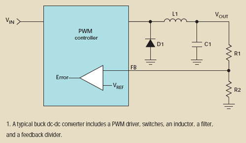
A typical buck dc-dc converter scheme includes a pulse-width modulation (PWM) driver, switches, an inductor, a filter, and a feedback divider (Fig. 1). The feedback voltage (FB) from the resistor divider R1 and R2 is a negative input for the error amplifier of the voltage control loop. In addition to the point-of-load regulation, the feedback divider also sets up the desired output voltage, VOUT. In other words, VOUT is programmable through an external resistor divider based on:

where VREF is a reference voltage and a positive input for the error amplifier.
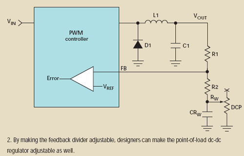
The minimum output voltage can be set as low as VREF, according to Equation 1. The resistor divider ratio, the input voltage, and the maximum duty cycle determine the maximum output. The reference voltage, VREF, can be obtained from the PWM controller datasheet. Thus, making the feedback divider adjustable makes the dc-dc regulator also adjustable (Fig. 2).

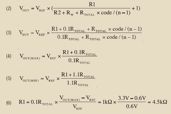
The adjustable output voltage of the dc-dc regulator can be expressed by Equation 2, where R1 and R2 are fixed resistors, RW is the wiper resistance, RTOTAL is the total resistance of the DCP, code is a decimal code of wiper position, and n is the total number of wiper taps.

The advantage of having the DCP in serial with the R2 resistor, rather than in parallel, is easier calculation of dc-dc output. It also prevents the bandwidth limitation that’s specific for the DCP. The DCP terminals have a parasitic capacitance of 10 to 25 pF, shown in Figure 2 as CRW. Connecting any of the DCP terminals to the FB node will cause phase shift and may decrease dc-dc regulator performance, such as transient response and stability.
The right DCP should be chosen to meet the application requirements based on knowing the VOUT adjusting range and desired resolution. For example, we would like to adjust the VOUT output voltage of a dc-dc regulator, built on the ISL85001 PWM controller, from 0.8 to 3.3 V.
The values of the DCP total resistance (RTOTAL) and resistors R1 and R2 can be derived from Equation 2. For simplicity it can be overwritten as Equation 3, where the wiper resistance is counted together with the R2 serial resistor. The suggested value of the R2 resistor should be less or equal to 0.1 × RTOTAL to have a bigger adjusting range (Equation 3, again). The maximum VOUT will be at code = 0 (Equation 4) and the minimum VOUT will be at max code = n – 1 (Equation 5).
According to a sample datasheet (from the ISL85001), the internal VREF = 0.6 V and the recommended value for the R1 resistor is from 1 to 10 kΩ. Since the number of RTOTAL values of the DCPs are limited, let’s select the RTOTAL = 10 kΩ first and then find R1 and R2 (Equation 6):
R1= 4.5k
R2 = 1 kΩ
Thus, the ideal DCP for this example should have an RTOTAL resistance of 10 kΩ and minimum wiper resistance.
Other features should be considered in choosing the appropriate DCP, such as the digital interface, nonvolatile programmability, RTOTAL tolerance, and temperature coefficient (TCr). Most of the available DCPs on the market have ±20% RTOTAL tolerance from part to part. That means each dc-dc regulator requires calibration, and the calibrated value of the wiper position can be stored in nonvolatile memory.
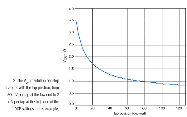
The perfect solution for dc-dc margining uses a 1% precision DCP, like the ISL22317, which eliminates the necessity of individual calibration and provides 0 Ω of wiper resistance and low TCr. Figure 3shows the VOUT curve versus the ISL22317W tap position. Since Equation 2 is a hyperbola, the VOUT resolution per step changes with the tap position, from 50 mV per tap at the low end to 2 mV per tap at the high end of the DCP settings in our example.
The ISL22317 features low TCr and 0 Ω of wiper resistance, complementing Intersil’s compensation scheme while also providing precision resistance settings from –40°C to 125°C.

Fixed DC-DC Regulator Output Uses A Digitally Controlled Potentiometer的更多相关文章
- PID DC/DC Converter Controller Using a PICmicro Microcontroller
http://www.microchip.com/stellent/idcplg?IdcService=SS_GET_PAGE&nodeId=1824&appnote=en011794 ...
- DC/DC与LDO的差别
转自:http://bbs.eetop.cn/thread-459121-1-1.html 在平时的学习中,我们都有接触LDO和DC/DC这一类的电源产品,但作为学生的我们队这些东西可能了解不够深刻, ...
- Simple dc/dc converter increases available power in dual-voltage system
The schematic in Figure 1 shows a way to increase the power available from a current-limited 5V supp ...
- Add margining capability to a dc/dc converter
You can easily add margining capability—that is, the ability to digitally adjust the output voltage— ...
- [专业名词·硬件] 2、DC\DC、LDO电源稳压基本常识(包含基本原理、高效率模块设计、常见问题、基于nRF51822电源管理模块分析等)·长文
综述先看这里 第一节的1.1简单介绍了DC/DC是什么: 第二节是关于DC/DC的常见的疑问答疑,非常实用: 第三节是针对nRF51822这款芯片电源管理部分的DC/DC.LDO.1.8的详细分析,对 ...
- Practice safe dc/dc converter
Short-circuit protection is an obvious requirement for a power supply, especially when its load conn ...
- LT1946A-- Transformerless dc/dc converter produces bipolar outputs
Dual-polarity supply provides ±12V from one IC VC (Pin 1): Error Amplifier Output Pin. Tie external ...
- DC DC降壓變換器ic 工作原理
目前DC/DC轉化器大致可分為:升壓型dc dc變化器.降壓型dc dc變化器及可升壓又可降壓dc dc變換器.我們今天主要提一下降壓型dc dc變換器的原理: 見下圖降壓變換器原理圖如圖1所示, 當 ...
- DC DC電路電感的選擇
注:只有充分理解電感在DC/DC電路中發揮的作用,才能更優的設計DC/DC電路.本文還包括對同步DC/DC及異步DC/DC概念的解釋. DCDC電路電感的選擇 簡介 在開關電源的設計中電感的設計為 ...
随机推荐
- KVC, KVO 实现原理
Key-Value Coding: 键值编码 (KVC) 方法调用: // 对象属性 // 类似: Person -> name setValue: forKey: // 对象的属性或者 属性的 ...
- curl错误码77 及 升级libcurl
今天碰到一个问题,curl请求返回错误码77错误 还给出了官网地址,网上查到77对应的是CURLE_SSL_CACERT_BADFILE 想起了刚默认更新了libcurl,于是有手工安装了一下c ...
- PHP laravel 5.0 Blade 模板引擎 Api使用备注
PHP laravel 5.0 Blade 模板引擎 Api使用备注 /** * PHP laravel 5.0 Blade 模板引擎 Api使用备注 **/ //子模版中开头,调用@extends( ...
- LightOJ - 1179 Josephus Problem(约瑟夫环)
题目链接:https://vjudge.net/contest/28079#problem/G 题目大意:约瑟夫环问题,给你n和k(分别代表总人数和每次要数到k),求最后一个人的位置. 解题思路:因为 ...
- ueditor 编辑器上传到服务器后图片上传不能正常使用
网站集成ueditor编辑器后在本地能正常使用,上传到服务器上后,图片上传功能提示:后端配置项没有正常加载,上传插件不能正常使用.且单个图片上传图标是灰色的不能点击. 相信遇到这个问题的同学是很多的吧 ...
- CSU 1425 Prime Summation
原题链接:http://acm.csu.edu.cn/OnlineJudge/problem.php?id=1425 DP题. f[i][j]表示当前数字为i,分解式中最大质数为j的方案数,那么,状态 ...
- 计算 Python (list or array) 相同索引元素相等的个数
上代码: a = [2, 3, 3, 1, 1, 3, 3, 3, 2, 1, 3, 1, 3, 2, 2, 2, 3, 1, 2, 3, 2, 3, 1, 1, 2, 1, 1, 1, 2, 2, ...
- python3环境下面bytes类型转换成字典类型实例
场景:通过http://tool.chinaz.com/tools/httptest.aspx在线HTTP接口测试工具获取接口的返回信息 { "status": 0, " ...
- ubuntu访问win10下的磁盘
在ubuntu下访问win10的磁盘时,提示出错. 先用命令查看一下磁盘挂载情况. sudo fdisk -l 会看到一些信息 我要访问的是E盘,也就是 /dev/sda6 这个分区 使用命令ntfx ...
- bzoj 1856 卡特兰数
复习了一下卡特兰数.. #include<bits/stdc++.h> #define LL long long #define fi first #define se second #d ...
