相机标定问题-Matlab & Py-Opencv
一、相机标定基本理论
1、相机成像系统介绍

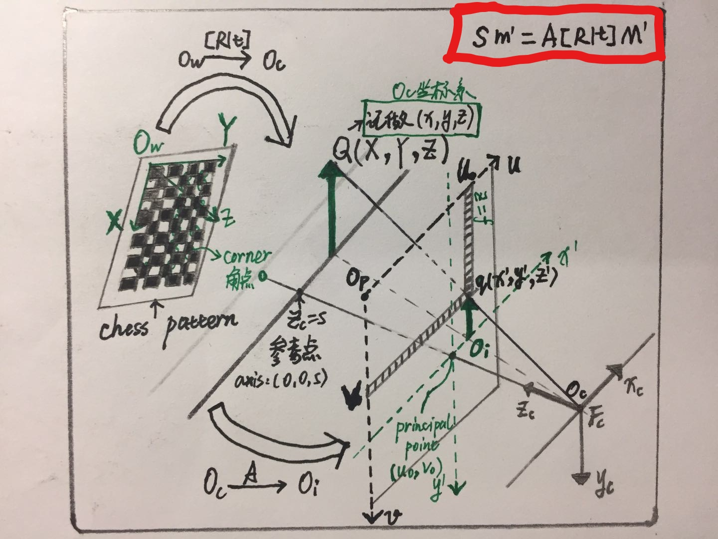
图中总共有4个坐标系:
- 图像坐标系:Op 坐标表示方法(u,v) Unit:Dots(个)
- 成像坐标系:Oi 坐标表示方法(x',y',z') Unit:mm(毫米)
- Camera坐标系:Oc 坐标表示方法(x,y,z) Unit:mm(毫米)
- World世界坐标系:Ow 坐标表示方法(X,Y,Z) Unit:mm(毫米)
图中所示的坐标转换关系:
{World世界坐标系:Ow }---Extrinsics [R|t]---{Camera坐标系:Oc}---Intrinsics A---{成像坐标系:Oi }---Liner Convert---{图像坐标系:Op }
这样就完成了世界坐标系中的点到图像坐标系的映射关系!
2、相机内参介绍
1、标准的针孔模型(针孔模型实际上没有焦距f,这里只是为了方便):

在实际计算过程中,为了计算方便,我们将像平面翻转平移到针孔前,从而得到一种数学上更为简单的等价形式(方便相似三角形的计算)
图1.标定全过程解析
这里的Q点实际上是O点对面的X点的位置,q实际为x的位置
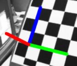
注意:由于世界坐标系的选定不是唯一的,因此为了方便起见,我们在Opencv使用的过程中,Ow世界坐标系选取的位置为标定板平面及其法线组成的三维空间坐标系,因此,世界坐标系中的所有的标定板上的点的Zw=0,所以在下面的python-Opencv程序中,我们角点的objpoints的取值Zw都为0,如旁边的小图所示:红色为Zw、蓝色为Yw、绿色为Xw
以Oc点为原点建立摄像机坐标系。点Q(x,y,z)为摄像机坐标系空间中的一点,该点被光线投影到图像平面Oi上的q(x',y',z')点,由于图像平面的位置再相机坐标系的焦点的位置,所以这里z‘=f,q点的坐标为(x',y',f)。
图像平面与光轴z轴垂直,和投影中心距离为f (f是相机的焦距)。按照三角比例关系可以得出:
 Formulation-001
注意这里的Zc实际上的值为s,下面的过程我们将会带入s数值
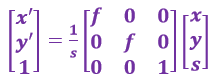
以上将坐标为(x,y,z)的Q点映射到投影平面上坐标为(x',y')的q点的过程称作投影变换
上述Q点到q点的变换关系用3*3的矩阵可表示为:q = A1Q ,其中
 Formulation-002
 Formulation-003
s*A1称为摄像机的内参数矩阵,单位均为物理尺寸(Units:mm)
通过上面,可以把相机坐标系转换到像图像坐标系的物理单位,即{Camera坐标系:Oc}---Intrinsics A1---{成像坐标系:Oi }
3、成像平面坐标系→像素坐标系
通过下面,可以把像平面坐标系物理单位到像素单位,即{成像坐标系:Oi }---Liner Convert---{图像坐标系:Op }
以图像平面的左上角或左下角为原点建立坐标系Op。假设像平面坐标系原点位于图像左下角,水平向右为u轴,垂直向上为v轴,均以像素为单位
以图像平面与光轴的交点Oi 为原点建立坐标系,水平向右为x轴,垂直向上为y轴。原点Oi 一般位于图像中心处,Oi 在以像素为单位的图像坐标系中的坐标为(u0, v0)
像平面坐标系和像素坐标系虽然在同一个平面上,但是原点并不是同一个。

设每个像素的物理尺寸大小为 dx * dy (mm) ( 由于单个像素点投影在图像平面上是矩形而不是正方形,因此可能dx != dy),
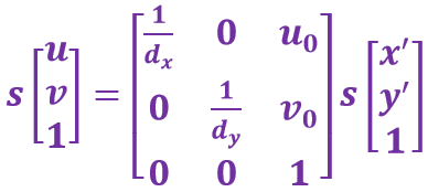
图像平面上某点在成像平面坐标系中的坐标为(x', y'),在像素坐标系中的坐标为(u, v),则二者满足如下关系:[即(x', y')→(u, v)]
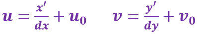 Formulation-004
用齐次坐标与矩阵形式表示为:
 Formulation-005
将等式两边都乘以点Q(x,y,zc)坐标中的Zc(也就是s)可得:
 Formulation-006
将摄像机坐标系中的Formulation-003 式代入上式可得:
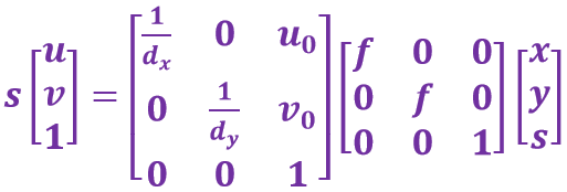 Formulation-007
则右边第一个矩阵和第二个矩阵的乘积亦为摄像机的内参数矩阵A(单位为像素),相乘后可得:
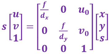 Formulation-008
和 Formulation-003 式相比,此内参数矩阵中f/dx, f/dy, u0, v0 的单位均为像素。令内参数矩阵为A,则上式可写成:
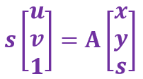 Formulation-009
三.相机内参A(与棋盘所在空间的3D几何无关)
在计算机视觉中,摄像机内参数矩阵
 Formulation-010
其中 f 为摄像机的焦距,单位一般是mm;dx,dy 为像元尺寸;u0,v0 为图像中心。
fx = f/dx, fy = f/dy,分别称为x轴和y轴上的归一化焦距.
为更好的理解f、dx、dy、fx、fy、u0、v0,举个实例:
现以NiKon D700相机为例进行求解其内参数矩阵:
焦距 f = 35mm 最高分辨率:4256×2832 传感器尺寸:36.0×23.9 mm
根据以上定义可以有:
u0= 4256/2 = 2128 v0= 2832/2 = 1416 dx = 36.0/4256 dy = 23.9/2832
fx = f/dx = 4137.8 fy = f/dy = 4147.3
分辨率可以从显示分辨率与图像分辨率两个方向来分类:
- 显示分辨率(屏幕分辨率)是屏幕图像的精密度,是指显示器所能显示的像素有多少。由于屏幕上的点、线和面都是由像素组成的,显示器可显示的像素越多,画面就越精细,同样的屏幕区域内能显示的信息也越多,所以分辨率是个非常重要的性能指标之一。可以把整个图像想象成是一个大型的棋盘,而分辨率的表示方式就是所有经线和纬线交叉点的数目。
- 显示分辨率一定的情况下,显示屏越小图像越清晰,反之,显示屏大小固定时,显示分辨率越高图像越清晰。图像分辨率则是单位英寸中所包含的像素点数,其定义更趋近于分辨率本身的定义。
3、相机外参介绍
旋转向量R=[Rx,Ry,Rz](大小为1×3的矢量或旋转矩阵3×3)和平移向量 t=(Tx,Ty,Tz)
旋转向量:旋转向量是旋转矩阵紧凑的变现形式,旋转向量为1×3的行矢量。
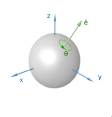
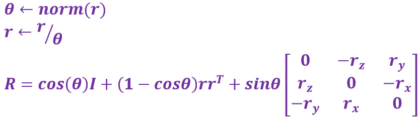 Formulation-011
r就是旋转向量,旋转向量的方向是旋转轴 ,旋转向量的模为围绕旋转轴旋转的角度,如图中的e向量,即旋转向量表现形式。
通过上面的公式,我们就可以求解出旋转矩阵R。同样的已知旋转矩阵,我们也可以通过下面的公式求解得到旋转向量:
 Fmulation-012
根据前面的 图1.相机标定全过程解析 中的变换方式,标定过程中的外参Extrinsics = [R|t],如下所示为[R|t]:
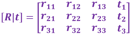 Formulation-013
则从世界坐标系变换到Q点的方式如下:
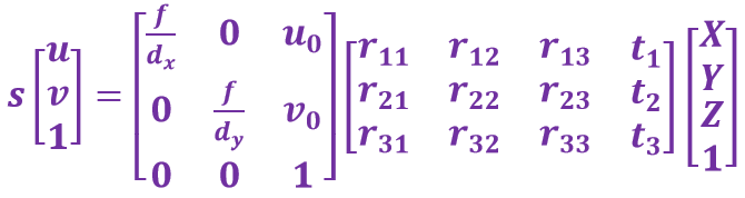 Formulation-014
即简写为如下形式:
 Formulation-015
4、畸变参数介绍
采用理想针孔模型,由于通过针孔的光线少,摄像机曝光太慢,在实际使用中均采用透镜,可以使图像生成迅速,但代价是引入了畸变。有两种畸变对投影图像影响较大: 径向畸变和切向畸变。
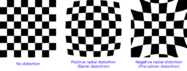
1、径向畸变
对某些透镜,光线在远离透镜中心的地方比靠近中心的地方更加弯曲,产生“筒形”或“鱼眼”现象,称为径向畸变。
一般来讲,成像仪中心的径向畸变为0,越向边缘移动,畸变越严重。不过径向畸变可以通过下面的泰勒级数展开式来校正:
xcorrected = x(1+k1r2+k2r4+k3r6)
ycorrected = y(1+k1r2+k2r4+k3r6)
这里(x, y)是畸变点在成像仪上的原始位置,r为该点距离成像仪中心的距离,(xcorrected ,ycorrected )是校正后的新位置。
对于一般的摄像机校正,通常使用泰勒级数中的前两项k1和k2就够了;对畸变很大的摄像机,比如鱼眼透镜,可以使用第三径向畸变项k3
无畸变 桶形畸变k1>0 枕形畸变k1<0
2、切向畸变
当成像仪被粘贴在摄像机的时候,会存在一定的误差,使得图像平面和透镜不完全平行,从而产生切向畸变。也就是说,如果一个矩形被投影到成像仪上时,可能会变成一个梯形。切向畸变可以通过如下公式来校正:
xcorrected = x + [ 2p1y + p2 (r2 + 2x2) ]
ycorrected = y + [ 2p2x + p1 (r2 + 2y2) ]
这里(x, y)是畸变点在成像仪上的原始位置,r为该点距离成像仪中心的距离,(xcorrected ,ycorrected )是校正后的新位置。

3、参数表示
x、y、xcorrected 、ycorrected 、r参数的表示如下图所示:

畸变系数的作用在于计算矫正之后的实际的成像平面位置,将得到的矫正公式带入到上述的计算公式Formulation-015式中即可得到矫正后的图像。
二、相机标定方法实践
1、采样标准pattern模板图像若干
 import cv2

 import glob

 import time

 import threading

 import numpy as np

 cap = cv2.VideoCapture(0)

 while not cap.isOpened(): # 检查摄像头是否打开成功

         time.sleep(100)

         print('Camera is Initialize...')

 width = int(cap.get(3)) # 读取摄像头分辨率参数

 height = int(cap.get(4))

 frame = np.zeros((width,height,3),dtype=np.uint8) # 创建图像模板

 ret, frame = cap.read()

 Key_val = 0 # 保存键值

 def Keybo_Moni(): # 按键测试函数

         count = 0

         while True:

                 global Key_val, frame, process_flag, cap

                 if Key_val == ord('r'):

                         Key_val= 0

                         cv2.imwrite('ResPic' + str(count) + '.jpg', frame) # 保存图像

                         count += 1

                         print('Get new pic %d' % count)

 try:

         Keybo_Moni_Thread = threading.Thread(target=Keybo_Moni, name='Keyboard-Thread') # 创建键盘监控线程

         Keybo_Moni_Thread.start() # 启动键盘监测线程

 except:

         print('Error:uqnable to start the thread!')

 while True:

         ret, frame = cap.read() # 读取视频帧

         cv2.imshow('Video_Show', frame) # 显示图像

         Key_val = cv2.waitKey(1) # 获取键值,不加此句,无法运行程序!(Ref:https://www.cnblogs.com/kissfu/p/3608016.html)

         if Key_val == ord('q'):

                 cv2.destroyAllWindows()

                 cap.release()

                 print('Pic Sample Finished!')

                 break
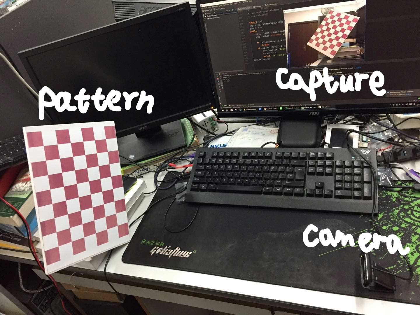
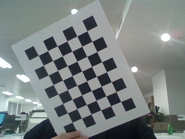
1)系统实际拍摄场景 2)硬件设备Logitech_Camera

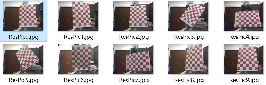
3)捕获素材如下所示(部分图像)
2、使用MATLAB工具箱进行相机标定
1)使用流程:
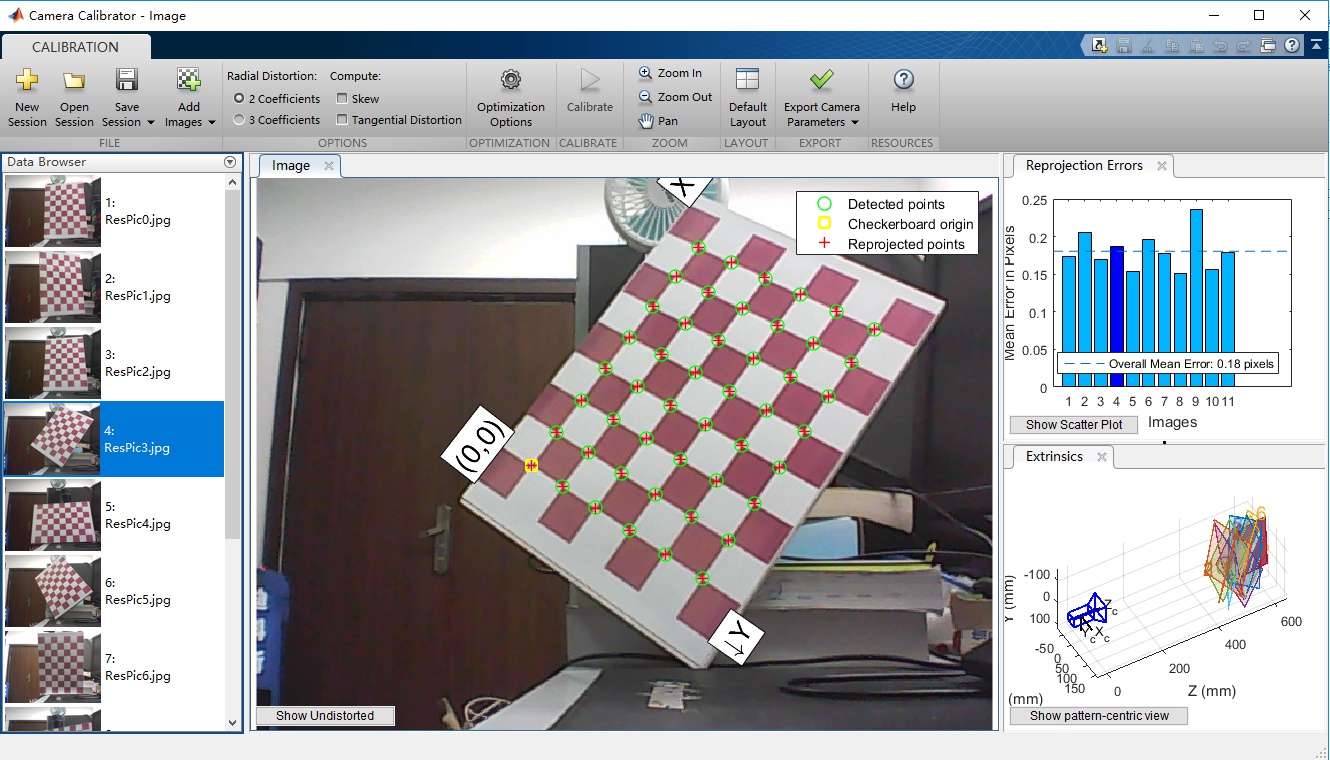
step1:打开Matlab 2015软件,上方栏目有一个应用程序,在应用程序下有一个工具箱,Camera Calibrator.
step2:打开工具箱,单击左上角的Add Images,选中捕获的所有的ResPic?.jpg,打开之后需要选择方块大小,取d=30mm.
step3:点击工具箱中间的绿色按钮Calibrate,单击开始我们的内参以及外参的计算和仿真,之后控制台输出Camera参数.
step4:我们可以选择到处MATLAB Script来分析Camera的标定流程.

2)仿真结果:
 cameraParams =

   cameraParameters (具有属性):

    Camera Intrinsics

                     IntrinsicMatrix: [3x3 double] part1:内参矩阵

                         FocalLength: [725.6633 724.1423] 焦距F

                      PrincipalPoint: [336.0815 233.9824] 主点P

                                Skew: 0

    Lens Distortion 镜头畸变

                    RadialDistortion: [0.0391 -0.3128] 径向畸变参数(k1,k2)  xcorrected = x(1+k1r2+k2r4+k3r6)  ycorrected = y(1+k1r2+k2r4+k3r6)

                TangentialDistortion: [0 0] 切向畸变参数(p1,p2)  xcorrected = x+[2p1y+p2(r2+2x2)]  ycorrected = y+[2p2x+p1(r2+2y2)]

    Camera Extrinsics 相机外参

                    RotationMatrices: [3x3x11 double] part2:世界外参旋转矩阵

                  TranslationVectors: [11x3 double] part3:世界外参平移矩阵

    Accuracy of Estimation  计算精度

               MeanReprojectionError: 0.1804

                  ReprojectionErrors: [48x2x11 double]

                   ReprojectedPoints: [48x2x11 double]

    Calibration Settings

                         NumPatterns: 11

                         WorldPoints: [48x2 double]

                          WorldUnits: 'mm'

                        EstimateSkew: 0

     NumRadialDistortionCoefficients: 2

        EstimateTangentialDistortion: 0
对上述脚本进行分析如下所示:
图中已经用红色标注出来了Lens的焦距f=725mm,主点分别为P=336mm和P`=234mm
part1:内参矩阵
图像参数 实际图像

从上图中的参数可知
a)相机CCD的点阵总个数为640*480(units:Dots),人工计算U0以及V0如下:(U0,V0)=(width/2,height/2)=(320,240)
b)注意这里的分辨率dpi是指显示器的dpi,和相机的像素尺寸无关,有关ppi和dpi的区别参考线面的链接。
part2:世界外参旋转矩阵
 val(:,:,1) = -0.0005 -0.9542 0.2991 0.9816 -0.0575 -0.1819 0.1908 0.2935 0.9367

 val(:,:,2) = -0.0406 -0.9795 0.1971 0.9472 0.0250 0.3195 -0.3179 0.1997 0.9269

 val(:,:,3) = 0.0217 -0.9162 0.4002 0.9898 -0.0368 -0.1378 0.1410 0.3991 0.9060

 val(:,:,4) = 0.5801 -0.7895 0.2002 0.7831 0.4730 -0.4039 0.2242 0.3911 0.8926 val(:,:,5) = 0.9954 -0.0478 -0.0836 0.0074 0.9032 -0.4291 0.0960 0.4265 0.8994

 val(:,:,6) = 0.4233 0.7063 -0.5674 -0.7637 0.6151 0.1959 0.4874 0.3504 0.7998 val(:,:,7) = -0.0189 -0.9922 -0.1236 0.9970 -0.0095 -0.0762 0.0745 -0.1247 0.9894

 val(:,:,8) = 0.8786 -0.0926 -0.4685 -0.0071 0.9784 -0.2068 0.4775 0.1851 0.8589

 val(:,:,9) = 0.0320 -0.9789 0.2020 0.7774 -0.1027 -0.6206 0.6282 0.1769 0.7577

 val(:,:,10) = 0.0167 -0.9229 0.3846 0.9836 -0.0541 -0.1723 0.1799 0.3811 0.9069

 val(:,:,11) = -0.5271 -0.7808 0.3356 0.8481 -0.4583 0.2658 -0.0537 0.4247 0.9038
外参旋转矩阵的来源在原理中已经介绍,每一个轴都需要旋转x,y,z旋转矩阵相乘之后就得到了如上所示的旋转矩阵参数!3*3的矩阵,最后任然为3*3.
part3:世界外参平移矩阵
外参平移矩阵主要用来对准棋盘图像的中心,T3=[dx,dy,dz]
MATLAB导出的脚本代码:Camera_Calibrator.m
 % Auto-generated by cameraCalibrator app on 13-Mar-2019

 %-------------------------------------------------------

 % Define images to process

 imageFileNames = {'D:\PythonDevelopment\Opencv_Test\data\ResPic0.jpg',...

     'D:\PythonDevelopment\Opencv_Test\data\ResPic1.jpg',...

     'D:\PythonDevelopment\Opencv_Test\data\ResPic2.jpg',...

     'D:\PythonDevelopment\Opencv_Test\data\ResPic3.jpg',...

     'D:\PythonDevelopment\Opencv_Test\data\ResPic4.jpg',...

     'D:\PythonDevelopment\Opencv_Test\data\ResPic5.jpg',...

     'D:\PythonDevelopment\Opencv_Test\data\ResPic6.jpg',...

     'D:\PythonDevelopment\Opencv_Test\data\ResPic7.jpg',...

     'D:\PythonDevelopment\Opencv_Test\data\ResPic8.jpg',...

     'D:\PythonDevelopment\Opencv_Test\data\ResPic9.jpg',...

     'D:\PythonDevelopment\Opencv_Test\data\ResPic10.jpg',...

     };

 % Detect checkerboards in images

 [imagePoints, boardSize, imagesUsed] = detectCheckerboardPoints(imageFileNames);

 imageFileNames = imageFileNames(imagesUsed);

 % Generate world coordinates of the corners of the squares

 squareSize = 30;  % in units of 'mm'

 worldPoints = generateCheckerboardPoints(boardSize, squareSize);

 % Calibrate the camera

 [cameraParams, imagesUsed, estimationErrors] = estimateCameraParameters(imagePoints, worldPoints, ...

     'EstimateSkew', false, 'EstimateTangentialDistortion', false, ...

     'NumRadialDistortionCoefficients', 2, 'WorldUnits', 'mm', ...

     'InitialIntrinsicMatrix', [], 'InitialRadialDistortion', []);

 % View reprojection errors

 h1=figure; showReprojectionErrors(cameraParams, 'BarGraph');

 % Visualize pattern locations

 h2=figure; showExtrinsics(cameraParams, 'CameraCentric');

 % Display parameter estimation errors

 displayErrors(estimationErrors, cameraParams);

 % For example, you can use the calibration data to remove effects of lens distortion.

 originalImage = imread(imageFileNames{1});

 undistortedImage = undistortImage(originalImage, cameraParams);

 % See additional examples of how to use the calibration data.  At the prompt type:

 % showdemo('MeasuringPlanarObjectsExample')

 % showdemo('StructureFromMotionExample')
3、采用Python及Opencv进行相机标定
注意标定板的方块大小Opencv是已知的30mm,根据Opencv官网给出的标定模板,打印在A4的纸上。
代码如下:
 import cv2

 import glob

 import time

 import threading

 import numpy as np

 print('Starting Capture...')

 cap = cv2.VideoCapture(0)

 while not cap.isOpened(): # 检查摄像头是否打开成功

         time.sleep(100)

         print('Camera is Initialize...')

 width = int(cap.get(3)) # 读取摄像头分辨率参数

 height = int(cap.get(4))

 frame = np.zeros((width,height,3),dtype=np.uint8) # 创建图像模板

 ret, frame = cap.read()

 Key_val = 0 # 保存键值

 def Keybo_Moni(): # 按键测试函数

         count = 0

         while True:

                 global Key_val, frame, process_flag, cap

                 if Key_val == ord('r'):

                         Key_val= 0

                         cv2.imwrite('ResPic' + str(count) + '.jpg', frame) # 保存图像

                         count += 1

                         print('Get new pic %d' % count)

 try:

         Keybo_Moni_Thread = threading.Thread(target=Keybo_Moni, name='Keyboard-Thread') # 创建键盘监控线程

         Keybo_Moni_Thread.start() # 启动键盘监测线程

 except:

         print('Error:uqnable to start the thread!')

 while True:

         ret, frame = cap.read() # 读取视频帧

         cv2.imshow('Video_Show', frame) # 显示图像

         Key_val = cv2.waitKey(1) # 获取键值,不加此句,无法运行程序!(Ref:https://www.cnblogs.com/kissfu/p/3608016.html)

         if Key_val == ord('q'):

                 cv2.destroyAllWindows()

                 cap.release()

                 print('Pic Sample Finished!')

                 break

 print('Starting CalibrateCamera...')

 # 标定算法开始

 # 设置寻找亚像素角点的参数,采用的停止准则是最大循环次数30和最大误差容限0.001

 criteria = (cv2.TERM_CRITERIA_EPS | cv2.TERM_CRITERIA_MAX_ITER, 30, 0.001)

 # 获取标定板角点的位置

 ojbp = np.zeros((6*7,3),np.float32)

 # reshape(-1,N)转换矩阵的为N列的矩阵,-1表示可以代表任意行

 # 比如有10个元素:

 # reshape(-1,1)==>10*1的矩阵

 # reshape(-1,2)===>5*2的矩阵

 # T 表示将矩阵当中的所有的元素全部顺序反转一遍

 # 将世界坐标系建在标定板上,所有点的Z坐标全部为0,所以只需要赋值x和y

 ojbp[:,:2] = np.mgrid[0:7,0:6].T.reshape(-1,2)

 objpoints = [] # 存储世界坐标系中的3D点(实际上Zw在标定板上的值为0)

 imgpoints = [] # 存储图像坐标系中的2D点

 images = glob.glob('*.jpg')

 for fname in images:

         img = cv2.imread(fname)

         gray = cv2.cvtColor(img, cv2.COLOR_RGB2GRAY)

         cv2.imshow('gray',gray)

         cv2.waitKey(300)

         # Find the chess board corners

         ret, corners = cv2.findChessboardCorners(gray, (7,6), flags=3)

         # If found, add object points, image points(after refining them)

         if ret == True:

                 if fname.find('ResPic') != -1:

                         time_name = str(int(time.time()))

                         cv2.imwrite(time_name+'.jpg',img)

                         os.remove(fname)

                 objpoints.append(ojbp)

                 corners2 = cv2.cornerSubPix(gray,corners,(11,11),(-1,-1),criteria) # 亚像素级焦点检测,基于提取的角点,进一步提高精确度

                 imgpoints.append(corners2)

                 # Draw and display the corners

                 img = cv2.drawChessboardCorners(img,(7,6),corners2,ret)

                 cv2.imshow('img',img)

                 cv2.waitKey(500)

         else:

                 os.remove(fname)

 cv2.destroyAllWindows()

 gray = cv2.cvtColor(cv2.imread(images[0]),cv2.COLOR_RGB2GRAY)

 ret, mtx, dist, rvecs, tvecs = cv2.calibrateCamera(objpoints, imgpoints, gray.shape[::-1],None,None)

 print('retval:\n',ret)

 print('Camera-Intrinsics:\n',mtx)

 print('Camera-Distortion:\n',dist)

 print('Camera-Extrinsics-R:')

 N = 1

 for r in rvecs:

         print('r'+str(N)+':',r[0],r[1],r[2])

         N += 1

 print('Camera-Extrinsics-t:')

 N = 1

 for t in tvecs:

         print('t'+str(N)+':',t[0],t[1],t[2])

         N += 1

 # Test The Result

 # The Picture need to Correct

 img = cv2.imread('./Calibsource/test2.jpg')

 cv2.imshow('img',img)

 cv2.waitKey(800)

 cv2.destroyAllWindows()

 h,  w = img.shape[:2]

 newcameramtx, roi=cv2.getOptimalNewCameraMatrix(mtx,dist,(w,h),1,(w,h))

 mothed = 'undistort'

 print('Starting Correct Photo...')

 if mothed != 'remapping':

         # undistort

         dst = cv2.undistort(img, mtx, dist, None, newcameramtx)

         x,y,w,h = roi

         print('ROI\'Param:', roi)

         dst1 = dst[y:y+h, x:x+w]

         cv2.imwrite('./Calibresult/calibresult.jpg',dst1)

 else:

         # undistort

         mapx,mapy = cv2.initUndistortRectifyMap(mtx,dist,None,newcameramtx,(w,h),5)

         dst = cv2.remap(img,mapx,mapy,cv2.INTER_CUBIC)

         # crop the image

         x,y,w,h = roi

         print('ROI\'Param:', roi)

         dst1 = dst[y:y+h, x:x+w]

         cv2.imwrite('./Calibresult/calibresult.jpg',dst1)

 # gesture_Draw

 print('Starting Gesture_Draw...')

 # 绘制简单的坐标系,调用此函数记得将下面的坐标修改为axis_axis

 axis_axis = np.float32([[3,0,0], [0,3,0], [0,0,-3]]).reshape(-1,3)

 # 绘制简单的坐标系,调用此函数记得将下面的坐标修改为axis_axis

 def draw_axis(img, corners, imgpts):

         corner = tuple(corners[0].ravel())

         img = cv2.line(img, corner, tuple(imgpts[0].ravel()), (255,0,0), 5)

         img = cv2.line(img, corner, tuple(imgpts[1].ravel()), (0,255,0), 5)

         img = cv2.line(img, corner, tuple(imgpts[2].ravel()), (0,0,255), 5)

         return img

 # 绘制立体方块在Pattern上,调用此函数记得将下面的坐标修改为axis_cube

 axis_cube = np.float32([[0,0,0], [0,3,0], [3,3,0], [3,0,0],[0,0,-3],[0,3,-3],[3,3,-3],[3,0,-3]])

 # 绘制立体方块在Pattern上,调用此函数记得将下面的坐标修改为axis_cube

 def draw_cube(img, corners, imgpts):

         imgpts = np.int32(imgpts).reshape(-1,2)

         # draw ground floor in green

         img = cv2.drawContours(img, [imgpts[:4]],-1,(0,255,0),-3)

         # draw pillars in blue color

         for i,j in zip(range(4),range(4,8)):

                 img = cv2.line(img, tuple(imgpts[i]), tuple(imgpts[j]),(255),3)

         # draw top layer in red color

         img = cv2.drawContours(img, [imgpts[4:]],-1,(0,0,255),3)

         return img

 criteria = (cv2.TERM_CRITERIA_EPS + cv2.TERM_CRITERIA_MAX_ITER, 30, 0.001)

 objp = np.zeros((6*7,3), np.float32)

 objp[:,:2] = np.mgrid[0:7,0:6].T.reshape(-1,2)

 images = glob.glob('*.jpg')

 if len(images) == 0:

         printf('No Test Picture can be loading!')

         exit()

 img = cv2.imread(images[0])

 gray = cv2.cvtColor(img, cv2.COLOR_RGB2GRAY)

 ret, corners = cv2.findChessboardCorners(gray, (7,6),None)

 if ret == True:

         corners2 = cv2.cornerSubPix(gray,corners,(11,11),(-1,-1),criteria)

         # Find the rotation and translation vectors.

         ret, rvecs, tvecs, inliers = cv2.solvePnPRansac(objp, corners2, mtx, dist)

         # project 3D points to image plane

         imgpts, jac = cv2.projectPoints(axis_cube, rvecs, tvecs, mtx, dist)

         img = draw_cube(img,corners2,imgpts)

         cv2.imshow('img',img)

         cv2.waitKey(800)

         cv2.imwrite('./Calibresult/gesture.png', img)

 cv2.destroyAllWindows()

 print('Gesture_Draw Finised')

 try:

         sys.exit(0)

 except:

         print('Program is dead.')

 finally:

         print('Clean-Up')
代码分析:
criteria:参数用来设置Opencv迭代计算的最小允许误差。
findChessboardCorners:函数用来找到对应的角点,(7,6)表示找7*6个角点在标定图上。
cornerSubPix:函数在找到的角点基础上更精确的寻找亚像素的角点位置并更新.(11,11)表示寻找的窗口大小。
drawChessboardCorners:函数在找到的角点模板上标出角点位置。
calibrateCamera:函数用来计算当前模型的内参和外参,相机畸变等信息。
getOptimalNewCameraMatrix:函数使用获得的相机的畸变参数对相机内参进行修正得到新得内参和截取图像的ROI窗口。
undistort:函数计算新的图像结果,结果与之前就算的ROI区域得到矫正后的图像。
标定函数API介绍:
a.标定图像角点检测:cv2.findChessboardCorners
 retval, corners    =cv.findChessboardCorners(image, patternSize[, corners[, flags]])

 参数:

 image:棋盘图像,8位灰度或彩色图像

 patternSize:棋盘的尺寸(注意应为内角点个数,内角点是和其他格子连着的点,边边上的不是!不是不是不是有几个方格!比如说“田”字只有一个内角点!)

 corners:存放角点的位置

 flags:迭代的准则

 返回值:

 retval:是否检测出角点

 corners:角点的位置
b.角点精确检测 cv2.cornerSubPix
 corners = cv.cornerSubPix(image, corners, winSize, zeroZone, criteria)

 参数:

 image:输入图像,8位或者float型

 corners:角点初始坐标。

 winsize:搜索窗口为2*winsize+1

 zerozone:死区,不计算区域,避免自相关矩阵的奇异性,没有死区,参数为(-1,-1)

 criteria:求角点的迭代终止条件

 返回值:

 corner:角点位置
c.显示角点位置:cv2.drawChessboardCorners
 image = cv.drawChessboardCorners(image, patternSize, corners, patternWasFound)

 patternWasFound:标志位,检测是否所有board都被检测到,若为是,则将角点连线,否则不连线
d.计算参数 cv2.calibrateCamera
 retval, cameraMatrix, distCoeffs, rvecs, tvecs = cv.calibrateCamera(objectPoints, imagePoints, imageSize, cameraMatrix, distCoeffs[, rvecs[, tvecs[, flags[,criteria]]]])

 参数:

 objectPoints:世界坐标系里的位置

 imagePoints: 像素坐标

 imageSize:为图像的像素尺寸大小

 flags:标定采用的算法

 criteria:迭代终止条件设定

 返回值:

 cameraMatrix:3*3矩阵,相机内参数矩阵

 disCoeffs:畸变矩阵

 rvecs:旋转向量

 tvecs:位移向量
e.矫正图像 cv2.getOptimalNewCameraMatrix
 retval,validPixROI=cv.getOptimalNewCameraMatrix(cameraMatrix,distCoeffs,imageSize, alpha[, newImgSize[, centerPrincipalPoint]])

 这个函数是为了微调参数,使图像不会在矫正过程中丢失很多像素,导致被矫正的过小。

 参数:

 imageSize:原始图像尺寸

 newImageSize:校正后图像尺寸

 alpha:取0或1。0返回剪裁后图像,1返回有黑色区域的图像,ROI是一个矩形框,圈出最优的裁切范围 参考:https://www.cnblogs.com/riddick/p/6711263.html

 centerPrincipalPoint:是否作用于中心。默认为opencv自己根据图像选择位置

 返回值:

 validPixROI:截图过程中的ROI区域参数
f.最终结果 cv2.undistort
 dst = cv.undistort(src, cameraMatrix, distCoeffs[, dst[, newCameraMatrix]])

 参数:

 scr:待矫正图片

 cameraMatrix:相机内参

 distCoeffs:畸变参数

 newCameraMatrix:矫正后的内参

 返回值:

 dst:输出图像
实验结果:
 retval:

  0.2208040557518684

 Camera-Intrinsics:

  [[616.76321725   0.         327.79663413]

  [  0.         615.46127457 226.00002854]

  [  0.           0.           1.        ]]

 Camera-Distortion:

  [[ 0.10478425 -0.30005988 -0.00268881  0.00525918  0.05811324]]

 Camera-Extrinsics-R:

 r1: [0.26699373] [0.36829143] [1.59609539]

 r2: [-0.08216888] [0.02643058] [1.5739028]

 r3: [0.6560576] [-0.11198011] [-2.9833505]

 r4: [0.05691746] [0.11485781] [-1.44155599]

 r5: [0.16876199] [0.54717179] [1.55050292]

 r6: [-0.08410575] [0.36611198] [1.91347658]

 r7: [0.41366115] [-0.25637666] [1.36897102]

 r8: [0.24991709] [-0.12493294] [2.03319431]

 Camera-Extrinsics-t:

 t1: [1.58486804] [-3.82773375] [14.50375578]

 t2: [1.78441286] [-3.92299521] [15.32974111]

 t3: [2.25776368] [2.77561687] [15.41762194]

 t4: [-3.76555275] [2.14859951] [15.0817749]

 t5: [5.30132186] [-1.28340352] [16.12856882]

 t6: [6.78619912] [0.42631112] [16.23319328]

 t7: [2.17053829] [-2.92354049] [11.15674799]

 t8: [4.3559293] [-0.99258867] [13.06667609]
参数中第二部分为摄像头内参:A = [[f/dx 0 u0], [0 f/dy v0], [0 0 1]]
第三部分为摄像头畸变参数:dist = [k1,k2,p1,p2[k3,[k4,k5,k6]]] 依次返回4个或5个或8个参数
第三部分为摄像头外参R:R = [[Vec1_x,Vec1_y,Vec1_z], [Vec2_x,Vec2_y,Vec3_z], ..., [Vecn_x,Vecn_y,Vecn_z]]
第四部分为摄像头外参T(平移参数):t = [[T1_x,T1_y,T1_z], [T2_x,T2_y,T2_z], ..., [Tn_x,Tn_y,Tn_z]]
测试使用的图像必须由原来的相机来采集图片,同时图像的大小必须相同,这样才能适应当前的相机内参&外参,采集代码如下:
 import cv2

 import glob

 import threading

 import numpy as np

 print('Starting Capture...')

 cap = cv2.VideoCapture(0)

 while not cap.isOpened(): # 检查摄像头是否打开成功

         time.sleep(100)

         print('Camera is Initialize...')

 width = int(cap.get(3)) # 读取摄像头分辨率参数

 height = int(cap.get(4))

 frame = np.zeros((width,height,3),dtype=np.uint8) # 创建图像模板

 ret, frame = cap.read()

 Key_val = 0 # 保存键值

 def Keybo_Moni(): # 按键测试函数

         count = 0

         while True:

                 global Key_val, frame, process_flag, cap

                 if Key_val == ord('r'):

                         Key_val= 0

                         cv2.imwrite('test' + str(count) + '.jpg', frame) # 保存图像

                         count += 1

                         print('Get new pic %d' % count)

 try:

         Keybo_Moni_Thread = threading.Thread(target=Keybo_Moni, name='Keyboard-Thread') # 创建键盘监控线程

         Keybo_Moni_Thread.start() # 启动键盘监测线程

 except:

         print('Error:uqnable to start the thread!')

 while True:

         ret, frame = cap.read() # 读取视频帧

         cv2.imshow('Video_Show', frame) # 显示图像

         Key_val = cv2.waitKey(1) # 获取键值,不加此句,无法运行程序!(Ref:https://www.cnblogs.com/kissfu/p/3608016.html)

         if Key_val == ord('q'):

                 cv2.destroyAllWindows()

                 cap.release()

                 print('Pic Sample Finished!')

                 break
原图像(size=640*480) convert 矫正图像(size=620*461)

三、其他扩展内容
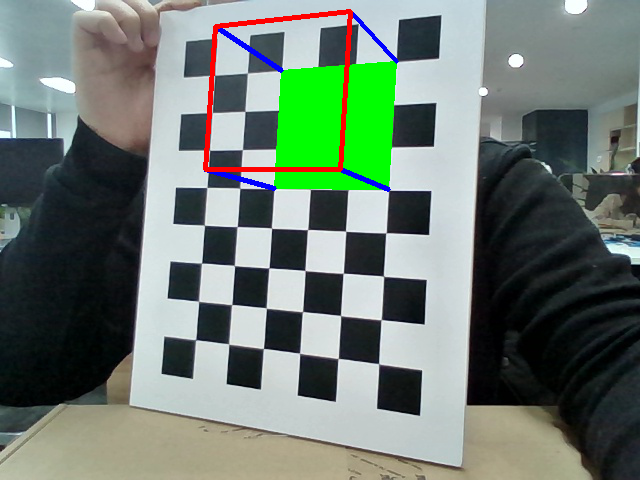
1、姿势估计
相关内容,完成上面的摄像机内参的相关内容之后,我们接下来在标定板上绘制我们的世界坐标系
在上述Python代码的最下放添加如下所示的代码,请注意,要选择能够提取角点的标定图像,由于某些采集的标定图像不能很好的返回角点,程序将会跳过第33行,我们将无法得到对应的效果,建议直接取之前标定过程中删选出来的图片作为姿势估计的图片源.
 print('Starting Gesture_Draw...')

 # 绘制简单的坐标系,调用此函数记得将下面的坐标修改为axis_axis

 axis_axis = np.float32([[3,0,0], [0,3,0], [0,0,-3]]).reshape(-1,3)

 # 绘制简单的坐标系,调用此函数记得将下面的坐标修改为axis_axis

 def draw_axis(img, corners, imgpts):

         corner = tuple(corners[0].ravel())

         img = cv2.line(img, corner, tuple(imgpts[0].ravel()), (255,0,0), 5)

         img = cv2.line(img, corner, tuple(imgpts[1].ravel()), (0,255,0), 5)

         img = cv2.line(img, corner, tuple(imgpts[2].ravel()), (0,0,255), 5)

         return img

 # 绘制立体方块在Pattern上,调用此函数记得将下面的坐标修改为axis_cube

 axis_cube = np.float32([[0,0,0], [0,3,0], [3,3,0], [3,0,0],[0,0,-3],[0,3,-3],[3,3,-3],[3,0,-3]])

 # 绘制立体方块在Pattern上,调用此函数记得将下面的坐标修改为axis_cube

 def draw_cube(img, corners, imgpts):

         imgpts = np.int32(imgpts).reshape(-1,2)

         # draw ground floor in green

         img = cv2.drawContours(img, [imgpts[:4]],-1,(0,255,0),-3)

         # draw pillars in blue color

         for i,j in zip(range(4),range(4,8)):

                 img = cv2.line(img, tuple(imgpts[i]), tuple(imgpts[j]),(255),3)

         # draw top layer in red color

         img = cv2.drawContours(img, [imgpts[4:]],-1,(0,0,255),3)

         return img

 criteria = (cv2.TERM_CRITERIA_EPS + cv2.TERM_CRITERIA_MAX_ITER, 30, 0.001)

 objp = np.zeros((6*7,3), np.float32)

 objp[:,:2] = np.mgrid[0:7,0:6].T.reshape(-1,2)

 img = cv2.imread('C:/Users/miao.ma/Desktop/Software/test.jpg')

 gray = cv2.cvtColor(img, cv2.COLOR_RGB2GRAY)

 ret, corners = cv2.findChessboardCorners(gray, (7,6),None)

 if ret == True:

         corners2 = cv2.cornerSubPix(gray,corners,(11,11),(-1,-1),criteria)

         # Find the rotation and translation vectors.

         ret, rvecs, tvecs, inliers = cv2.solvePnPRansac(objp, corners2, mtx, dist)

         # project 3D points to image plane

         imgpts, jac = cv2.projectPoints(axis_cube, rvecs, tvecs, mtx, dist)

         img = draw_cube(img,corners2,imgpts)

         cv2.imshow('img',img)

         cv2.waitKey(800)

         cv2.imwrite('C:/Users/miao.ma/Documents/Python Scripts/Calibresult/gesture.png', img)

 cv2.destroyAllWindows()

 print('Gesture_Draw Finised')
两种绘制的结果如下图所示:

2、单目测距
待补充~欢迎评论,大家有什么好的建议和意见都可以一起来讨论一下,完善一下相机标定的相关内容,为后面的双目相机的标定做好准备!
四、参考文献&参看链接
相机标定实践操作流程(Methods using Camera Parameter):https://i-beta.cnblogs.com/posts/edit-done;postId=12703897
相机标定Reference01:https://www.cnblogs.com/Jessica-jie/p/6596450.html
相机标定Reference02:https://www.cnblogs.com/Undo-self-blog/p/8448500.html
相机标定Reference03:http://www.vision.caltech.edu/bouguetj/calib_doc/htmls/example.html
PPI(Pixle per inch) DPI(Dots per inch)之间的区别Reference04:https://www.cnblogs.com/icmzn/p/7295343.html
相关空间坐标,相机坐标,图像坐标解释参看Reference05:https://blog.csdn.net/liulina603/article/details/52953414
三维空间旋转,三维旋转矩阵的向量表示方法参考Resference06:https://blog.csdn.net/wu_wenhuan/article/details/52588921
cv2中的计算内参外参函数calibrateCamera实现原理Reference07:https://blog.csdn.net/u010368556/article/details/79434240
弹幕测距参考Reference08:https://blog.csdn.net/m0_37811342/article/details/80394935
转载参考Reference09:https://www.cnblogs.com/Jessica-jie/p/6596450.html
相关文件参考我的博客园文件:https://files.cnblogs.com/files/uestc-mm/Camera_calibration.7z
标定模板下载:https://files.cnblogs.com/files/uestc-mm/%E6%A0%87%E5%AE%9A%E6%A8%A1%E6%9D%BFpattern.pdf
如果您觉得看完有所收获,欢迎扫一扫,可以资助一分,几分money,不在乎多少(我也是跟网上的大神们学的),不想挣钱娶媳妇的程序员不是好程序员,谢谢

相机标定问题-Matlab & Py-Opencv的更多相关文章
- 相机标定:Matlab标定工具箱使用要点
1.单目标定 1.核心步骤 (1)获得标定数据:<Images_names>, <Read images>, <Extract grid corners> 1)输入 ...
- 相机标定 matlab opencv ROS三种方法标定步骤(2)
二 ubuntu下Opencv的相机标定 一般直接用Opencv的源码就可以进行相机的标定,但是可能只是会实现结果,却不懂实现的过程,我也是模模糊糊的看了<计算机视觉中的多视图几何>以及 ...
- 【视频开发】【计算机视觉】相机标定(Camera calibration)原理、步骤
相机标定(Camera calibration)原理.步骤 author@jason_ql(lql0716) http://blog.csdn.net/lql0716 在图像测量过程以及机器视觉应用 ...
- 相机标定 matlab opencv ROS三种方法标定步骤(3)
三 , ROS 环境下 如何进行相机标定 刚开始做到的时候遇到一些问题没有记录下来,现在回头写的时候都是没有错误的结果了,首先使用ROS标定相机, 要知道如何查看节点之间的流程图 rosrun r ...
- 相机标定 matlab opencv ROS三种方法标定步骤(1)
一 . 理解摄像机模型,网上有很多讲解的十分详细,在这里我只是记录我的整合出来的资料和我的部分理解 计算机视觉领域中常见的三个坐标系:图像坐标系,相机坐标系,世界坐标系,实际上就是要用矩阵来表 示各个 ...
- 相机标定过程(opencv) + matlab参数导入opencv + matlab标定和矫正
%%%%%%%%%%%%%%%%%%%%%%%%%%%%%%%%%%%%%%%%%% 辛苦原创所得,转载请注明出处 %%%%%%%%%%%%%%%%%%%%%%%%%%%%%%%%%%%%%%%%%% ...
- OpenCV相机标定
标签(空格分隔): Opencv 相机标定是图像处理的基础,虽然相机使用的是小孔成像模型,但是由于小孔的透光非常有限,所以需要使用透镜聚焦足够多的光线.在使用的过程中,需要知道相机的焦距.成像中心以及 ...
- Opencv——相机标定
相机标定的目的:获取摄像机的内参和外参矩阵(同时也会得到每一幅标定图像的选择和平移矩阵),内参和外参系数可以对之后相机拍摄的图像就进行矫正,得到畸变相对很小的图像. 相机标定的输入:标定图像上所有内角 ...
- 使用OpenCV进行相机标定
1. 使用OpenCV进行标定 相机已经有很长一段历史了.但是,伴随着20世纪后期的廉价针孔照相机的问世,它们已经变成我们日常生活的一种常见的存在.不幸的是,这种廉价是由代价的:显著的变形.幸运的是, ...
随机推荐
- 使用容器编排工具docker swarm安装clickhouse多机集群
1.首先需要安装docker最新版,docker 目前自带swarm容器编排工具 2.选中一台机器作为master,执行命令sudo docker swarm init [options] 3,再需 ...
- iview服务不可以被访问解决办法
一般情况是因为服务的host设置为localhsot了,修改为0.0.0.0即可. 打开...\iview-admin-dev\node_modules\webpack-dev-server\bin下 ...
- linux 上安装图形界面
linux 上安装 vncserver 后,图形界面里只有灰底和一个terminal 框, 解决方法: 修改 .vnc/xstartup为 unset SESSION_MANAGER # exec / ...
- input下拉带输入框
html5 自带的datalist实现 html代码: <input list="students"> <datalist id="students&q ...
- 通过DeviceIoControl读磁盘的方式读取独占文件内容
前言 windows操作系统中常见的一个文件存储系统是NTFS.在这个文件系统中MFT是它的核心. 图一 MFT是一个数据结构,上图是它的结构,它主要用来存放每个文件和目录在磁 ...
- linux文件常用命令
文件管理不外乎文件或目录的创建.删除.查询.移动,有mkdir/rm/mv 2.1. 创建和删除 创建:mkdir 删除:rm 删除非空目录:rm -rf file目录 删除日志 rm *log (等 ...
- linux oops调试
参考文章: arm 指令定位错误 https://blog.csdn.net/songcdut/article/details/41383483 linux mips指令学习 https://www. ...
- angular Observable
1.回调函数 /** 1.设计实现函数 */ print_msg(msg) { console.log(msg); } /** 2.设计调用函数,param1:实现函数参数,param2:实现函数本身 ...
- 2018-2019-1 20165231 实现mypwd(选做)
实现mypwd 要求: 学习pwd命令 研究pwd实现需要的系统调用(man -k; grep),写出伪代码 实现mypwd 测试mypwd pwd: 在Linux层次结构中,想要知道当前所处的目录, ...
- codeforces 1151 A
一个让我爆零的水题,,,,, codeforces 1151A 1000分 题意:一个字符串,单个字符可以一步可以变成左右两个(Z可以变成Y,A),问最低多少步可以产生“ACTG”: 错因:错误的 ...