数字麦克风PDM信号采集与STM32 I2S接口应用(四)--单片机源码
本文是数字麦克风笔记文章的单片机程序。一些朋友私信我,调试出问题。
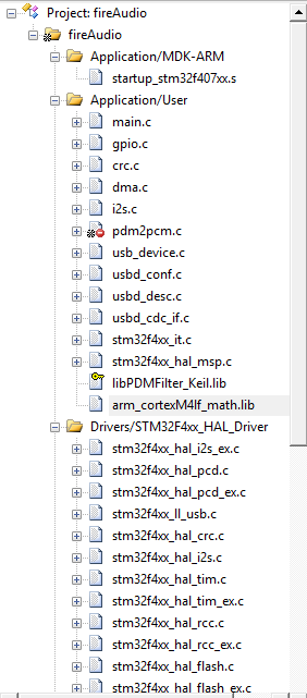
我就把源码贴出来吧,可能主要问题是DMA的配置。
尤其双DMA时候,需要手动启动I2S的接收DMA,HAL库没有这个接口,不看datasheet是找不到这个毛病的,这也是HAL库用多了引起的问题,一些特底层的问题大家都不愿意去搞了。


/* USER CODE BEGIN Header */
/**
******************************************************************************
* @file : main.c
* @brief : Main program body
******************************************************************************
* @attention
*
* <h2><center>© Copyright (c) 2019 STMicroelectronics.
* All rights reserved.</center></h2>
*
* This software component is licensed by ST under Ultimate Liberty license
* SLA0044, the "License"; You may not use this file except in compliance with
* the License. You may obtain a copy of the License at:
* www.st.com/SLA0044
*
******************************************************************************
*/
/* USER CODE END Header */ /* Includes ------------------------------------------------------------------*/
#include "main.h"
#include "crc.h"
#include "dma.h"
#include "i2s.h"
//#include "pdm2pcm.h"
#include "usb_device.h"
#include "gpio.h" /* Private includes ----------------------------------------------------------*/
/* USER CODE BEGIN Includes */
#include "usbd_cdc_if.h"
#include <stdio.h>
#include "pdm_filter.h"
#include "arm_math.h"
/* USER CODE END Includes */ /* Private typedef -----------------------------------------------------------*/
/* USER CODE BEGIN PTD */
/*
---- 12khz
% Discrete-Time IIR Filter (real)
% -------------------------------
% Filter Structure : Direct-Form I, Second-Order Sections
% Number of Sections : 3
% Stable : Yes
% Linear Phase : No SOS Matrix:
1 -2 1 1 1.195433962890738 0.69059892324149696
1 -2 1 1 0.94280904158206325 0.33333333333333331
1 -2 1 1 0.84028692165132668 0.18834516088404465 Scale Values:
0.12379124008768976
0.097631072937817504
0.087014559808179473 --- 2khz
% Generated by MATLAB(R) 8.3 and the Signal Processing Toolbox 6.21.
% Generated on: 23-Jul-2019 18:13:58 % Coefficient Format: Decimal % Discrete-Time IIR Filter (real)
% -------------------------------
% Filter Structure : Direct-Form I, Second-Order Sections
% Number of Sections : 3
% Stable : Yes
% Linear Phase : No SOS Matrix:
1 -2 1 1 -1.6812394272942188 0.81976044292731376
1 -2 1 1 -1.454243586251585 0.57406191508395488
1 -2 1 1 -1.349079994888392 0.46023366403769816 Scale Values:
0.8752499675553832
0.75707637533388505
0.70232841473152252
*/ #define numStages 3 // 6 order
#define FILTER_SAMPLES 2*160
float32_t FilterDataIn[FILTER_SAMPLES]={};
float32_t FilterDataOut[FILTER_SAMPLES]={}; static float32_t testInput_f32_50Hz_200Hz[FILTER_SAMPLES]; /* input samping points */
static float32_t testOutput[FILTER_SAMPLES]; /* output */
static float32_t IIRStateF32[*numStages]; /* tmp buf=numTaps + blockSize - 1*/ #if 1 // 12khz hpf
const float32_t IIRCoeffs32HP[*numStages] = {
1.0f, -2.0f, 1.0f, -1.195433962890738f, -0.69059892324149696f,
1.0f, -2.0f, 1.0f, -0.94280904158206325f, -0.33333333333333331f,
1.0f, -2.0f, 1.0f, -0.84028692165132668f, -0.18834516088404465f
};
const float32_t ScaleValue = 0.12379124008768976f * 0.097631072937817504f * 0.087014559808179473f;
#else // 2khz hpf, people can hear the sound, just high pitch.
const float32_t IIRCoeffs32HP[*numStages] = {
1.0f, -2.0f, 1.0f, 1.6812394272942188, -0.81976044292731376,
1.0f, -2.0f, 1.0f, 1.454243586251585, -0.57406191508395488,
1.0f, -2.0f, 1.0f, 1.349079994888392, -0.46023366403769816
};
const float32_t ScaleValue = 0.8752499675553832f * 0.75707637533388505f * 0.70232841473152252f;
#endif void arm_copy_u162f32(
int16_t * pSrc,
float32_t * pDst,
uint32_t blockSize)
{
uint32_t blkCnt; /* loop counter */ #ifndef ARM_MATH_CM0 /* Run the below code for Cortex-M4 and Cortex-M3 */ /*loop Unrolling */
blkCnt = blockSize >> 2u; /* First part of the processing with loop unrolling. Compute 4 outputs at a time.
** a second loop below computes the remaining 1 to 3 samples. */
while(blkCnt > 0u)
{
/* C = A */
/* Copy and then store the results in the destination buffer */
*pDst++ = *pSrc++;
*pDst++ = *pSrc++;
*pDst++ = *pSrc++;
*pDst++ = *pSrc++; /* Decrement the loop counter */
blkCnt--;
} /* If the blockSize is not a multiple of 4, compute any remaining output samples here.
** No loop unrolling is used. */
blkCnt = blockSize % 0x4u; #else /* Run the below code for Cortex-M0 */ /* Loop over blockSize number of values */
blkCnt = blockSize; #endif /* #ifndef ARM_MATH_CM0 */ while(blkCnt > 0u)
{
/* C = A */
/* Copy and then store the results in the destination buffer */
*pDst++ = *pSrc++; /* Decrement the loop counter */
blkCnt--;
}
} void arm_copy_f322u16(
float32_t * pSrc,
int16_t * pDst,
uint32_t blockSize)
{
uint32_t blkCnt; /* loop counter */ #ifndef ARM_MATH_CM0 /* Run the below code for Cortex-M4 and Cortex-M3 */ /*loop Unrolling */
blkCnt = blockSize >> 2u; /* First part of the processing with loop unrolling. Compute 4 outputs at a time.
** a second loop below computes the remaining 1 to 3 samples. */
while(blkCnt > 0u)
{
/* C = A */
/* Copy and then store the results in the destination buffer */
*pDst++ = (int16_t)*pSrc++;
*pDst++ = (int16_t)*pSrc++;
*pDst++ = (int16_t)*pSrc++;
*pDst++ = (int16_t)*pSrc++; /* Decrement the loop counter */
blkCnt--;
} /* If the blockSize is not a multiple of 4, compute any remaining output samples here.
** No loop unrolling is used. */
blkCnt = blockSize % 0x4u; #else /* Run the below code for Cortex-M0 */ /* Loop over blockSize number of values */
blkCnt = blockSize; #endif /* #ifndef ARM_MATH_CM0 */ while(blkCnt > 0u)
{
/* C = A */
/* Copy and then store the results in the destination buffer */
*pDst++ = (int16_t)*pSrc++; /* Decrement the loop counter */
blkCnt--;
}
} /* USER CODE END PTD */ /* Private define ------------------------------------------------------------*/
/* USER CODE BEGIN PD */ /* USER CODE END PD */ /* Private macro -------------------------------------------------------------*/
/* USER CODE BEGIN PM */ /* USER CODE END PM */ /* Private variables ---------------------------------------------------------*/ /* USER CODE BEGIN PV */ /* USER CODE END PV */ /* Private function prototypes -----------------------------------------------*/
void SystemClock_Config(void);
/* USER CODE BEGIN PFP */ /* USER CODE END PFP */ /* Private user code ---------------------------------------------------------*/
/* USER CODE BEGIN 0 */
#define PDM_2_PCM_SAM (2*64)
#define PDM_SAM_POINTS (2*640)
#define PCM_SAM_POINTS (2*160)
typedef struct {
int pdmIdx;
int pcmIdx;
uint16_t PDMBuf[][PDM_SAM_POINTS];
int16_t PCMBuf[PCM_SAM_POINTS];
}MicrophoneBufStruct; MicrophoneBufStruct MicrophoreBuf = {};
PDMFilter_InitStruct Filter; void HAL_I2S_DMA_RxM0CpltCallback(DMA_HandleTypeDef *hdma);
void HAL_I2S_DMA_RxM1CpltCallback(DMA_HandleTypeDef *hdma);
void HAL_I2S_DMA_Rx_Error_CpltCallback(DMA_HandleTypeDef *hdma);
int UsbTxErr = ;
uint8_t printBuf[PCM_SAM_POINTS*]={};
int tests = ; static int32_t idx = ;
/* USER CODE END 0 */ /**
* @brief The application entry point.
* @retval int
*/
int main(void)
{
/* USER CODE BEGIN 1 */
/* USER CODE END 1 */ /* MCU Configuration--------------------------------------------------------*/ /* Reset of all peripherals, Initializes the Flash interface and the Systick. */
HAL_Init(); /* USER CODE BEGIN Init */ /* USER CODE END Init */ /* Configure the system clock */
SystemClock_Config(); /* USER CODE BEGIN SysInit */ /* USER CODE END SysInit */ /* Initialize all configured peripherals */
MX_GPIO_Init();
MX_DMA_Init();
MX_I2S2_Init();
MX_USB_DEVICE_Init();
MX_CRC_Init();
// MX_PDM2PCM_Init();
/* USER CODE BEGIN 2 */
HAL_Delay();
/* USER CODE END 2 */ /* Infinite loop */
/* USER CODE BEGIN WHILE */
__HAL_RCC_GPIOB_CLK_ENABLE();
//PB0 : FOR MEAS IIS SAMPING TIME
GPIO_InitTypeDef GPIO_InitStruct = {};
GPIO_InitStruct.Pin = GPIO_PIN_0;
GPIO_InitStruct.Mode = GPIO_MODE_OUTPUT_PP;
GPIO_InitStruct.Pull = GPIO_PULLUP;
GPIO_InitStruct.Speed = GPIO_SPEED_FREQ_HIGH;
HAL_GPIO_Init(GPIOB, &GPIO_InitStruct);
HAL_GPIO_WritePin( GPIOB, GPIO_PIN_0, ); /* Filter LP & HP Init */ //Õâ¸öÂ˲¨Æ÷Ч¹û±È½Ï²î£¬×Ô¼ºÂ˲¨²ÅÐУ¬³öÏÖÔëÉùºÍÌø±ä¡£
Filter.HP_HZ = ;
Filter.LP_HZ = ;
Filter.Fs = ;
Filter.Out_MicChannels = ;
Filter.In_MicChannels = ;
PDM_Filter_Init((PDMFilter_InitStruct *)&Filter); hi2s2.hdmarx->XferCpltCallback = HAL_I2S_DMA_RxM0CpltCallback;
hi2s2.hdmarx->XferM1CpltCallback = HAL_I2S_DMA_RxM1CpltCallback;
hi2s2.hdmarx->XferErrorCallback = HAL_I2S_DMA_Rx_Error_CpltCallback;
HAL_DMAEx_MultiBufferStart_IT(hi2s2.hdmarx, (uint32_t)&hi2s2.Instance->DR,
(uint32_t)&MicrophoreBuf.PDMBuf[], (uint32_t)&MicrophoreBuf.PDMBuf[], PDM_SAM_POINTS);
HAL_I2S_DMAResume(&hi2s2);
/* Enable Rx DMA Request */
SET_BIT(hi2s2.Instance->CR2, SPI_CR2_RXDMAEN); // HAL_I2S_Receive_DMA (&hi2s2, MicrophoreBuf.PDMBuf[0], PDM_SAM_POINTS);
static char printBuf[]={};
static int cur_buf = ;
HAL_GPIO_WritePin( GPIOB, GPIO_PIN_0, ); arm_biquad_casd_df1_inst_f32 S = {};
arm_biquad_cascade_df1_init_f32(&S, numStages, (float32_t *)&IIRCoeffs32HP[], (float32_t *)&IIRStateF32[]);
while ()
{
uint16_t *srcBuf = ;
int16_t *dstBuf = ; if(MicrophoreBuf.pdmIdx == -) continue; dstBuf = MicrophoreBuf.PCMBuf; srcBuf = MicrophoreBuf.PDMBuf[MicrophoreBuf.pdmIdx];
MicrophoreBuf.pdmIdx = -;
for(int i=; i<PDM_SAM_POINTS; i++)
{
uint16_t a = srcBuf[i];
srcBuf[i] = HTONS(a);
}
uint16_t volumeGain = ;
int num = ; HAL_GPIO_WritePin( GPIOB, GPIO_PIN_0, );
for(int i=; i<PDM_SAM_POINTS; i=i+PDM_2_PCM_SAM)
{
num += PDM_Filter_64_LSB((uint8_t *)&srcBuf[i], (uint16_t *)&dstBuf[i/], volumeGain , (PDMFilter_InitStruct *)&Filter);
}
HAL_GPIO_WritePin( GPIOB, GPIO_PIN_0, ); // USE IIR FILTER HERE
#if 1
//HAL_GPIO_WritePin( GPIOB, GPIO_PIN_0, 1);
arm_copy_u162f32(dstBuf, FilterDataIn, FILTER_SAMPLES);
arm_biquad_cascade_df1_f32(&S, FilterDataIn, FilterDataOut, FILTER_SAMPLES);
arm_scale_f32(FilterDataOut, ScaleValue, FilterDataOut, FILTER_SAMPLES);
arm_copy_f322u16(FilterDataOut, dstBuf, FILTER_SAMPLES);
//HAL_GPIO_WritePin( GPIOB, GPIO_PIN_0, 0);
#endif #if 0 // send raw data to pc
if(USBD_OK != CDC_Transmit_FS((uint8_t *)dstBuf, *PCM_SAM_POINTS) )
{
UsbTxErr++;
// HAL_Delay(1);
// CDC_Transmit_FS((uint8_t *)dstBuf, PCM_SAM_POINTS);
}
#endif #if 1 // calc fire trigger.
float32_t calcRst = 0.0f;
uint8_t triggerFired = ;
HAL_GPIO_WritePin( GPIOB, GPIO_PIN_0, );
for(int i=; i<; i++)
{
int offset = i*FILTER_SAMPLES/;
arm_abs_f32(FilterDataOut + offset, FilterDataOut + offset, FILTER_SAMPLES/);
arm_mean_f32(FilterDataOut+ offset, FILTER_SAMPLES/, &calcRst);
if(((int)calcRst >) && (triggerFired == ))
{
triggerFired = ;
break;
}
}
HAL_GPIO_WritePin( GPIOB, GPIO_PIN_0, );
uint8_t cmd[] = { ,,,,
,,,,
,,,, , ,};
cmd[] = triggerFired<<; // 0x80 null, 0x81 sound, 0x82 acc, 0x83 all.
cmd[] = (uint8_t)(((int)calcRst) & 0xff);
cmd[] = (uint8_t)(((int)calcRst) >> );
if(USBD_OK != CDC_Transmit_FS((uint8_t *)cmd, sizeof(cmd) ) )
{
UsbTxErr++;
} #endif }
/* USER CODE END WHILE */ /* USER CODE BEGIN 3 */ /* USER CODE END 3 */
} /**
* @brief System Clock Configuration
* @retval None
*/
void SystemClock_Config(void)
{
RCC_OscInitTypeDef RCC_OscInitStruct = {};
RCC_ClkInitTypeDef RCC_ClkInitStruct = {};
RCC_PeriphCLKInitTypeDef PeriphClkInitStruct = {}; /** Configure the main internal regulator output voltage
*/
__HAL_RCC_PWR_CLK_ENABLE();
__HAL_PWR_VOLTAGESCALING_CONFIG(PWR_REGULATOR_VOLTAGE_SCALE1);
/** Initializes the CPU, AHB and APB busses clocks
*/
RCC_OscInitStruct.OscillatorType = RCC_OSCILLATORTYPE_HSE;
RCC_OscInitStruct.HSEState = RCC_HSE_ON;
RCC_OscInitStruct.PLL.PLLState = RCC_PLL_ON;
RCC_OscInitStruct.PLL.PLLSource = RCC_PLLSOURCE_HSE;
RCC_OscInitStruct.PLL.PLLM = ;
RCC_OscInitStruct.PLL.PLLN = ;
RCC_OscInitStruct.PLL.PLLP = RCC_PLLP_DIV2;
RCC_OscInitStruct.PLL.PLLQ = ;
if (HAL_RCC_OscConfig(&RCC_OscInitStruct) != HAL_OK)
{
Error_Handler();
}
/** Initializes the CPU, AHB and APB busses clocks
*/
RCC_ClkInitStruct.ClockType = RCC_CLOCKTYPE_HCLK|RCC_CLOCKTYPE_SYSCLK
|RCC_CLOCKTYPE_PCLK1|RCC_CLOCKTYPE_PCLK2;
RCC_ClkInitStruct.SYSCLKSource = RCC_SYSCLKSOURCE_PLLCLK;
RCC_ClkInitStruct.AHBCLKDivider = RCC_SYSCLK_DIV1;
RCC_ClkInitStruct.APB1CLKDivider = RCC_HCLK_DIV4;
RCC_ClkInitStruct.APB2CLKDivider = RCC_HCLK_DIV2; if (HAL_RCC_ClockConfig(&RCC_ClkInitStruct, FLASH_LATENCY_5) != HAL_OK)
{
Error_Handler();
}
PeriphClkInitStruct.PeriphClockSelection = RCC_PERIPHCLK_I2S;
PeriphClkInitStruct.PLLI2S.PLLI2SN = ;
PeriphClkInitStruct.PLLI2S.PLLI2SR = ;
if (HAL_RCCEx_PeriphCLKConfig(&PeriphClkInitStruct) != HAL_OK)
{
Error_Handler();
}
} /* USER CODE BEGIN 4 */
static void DMA_SetConfig(DMA_HandleTypeDef *hdma, uint32_t SrcAddress, uint32_t DstAddress, uint32_t DataLength)
{
/* Clear DBM bit */
hdma->Instance->CR &= (uint32_t)(~DMA_SxCR_DBM); /* Configure DMA Stream data length */
hdma->Instance->NDTR = DataLength; /* Memory to Peripheral */
if((hdma->Init.Direction) == DMA_MEMORY_TO_PERIPH)
{
/* Configure DMA Stream destination address */
hdma->Instance->PAR = DstAddress; /* Configure DMA Stream source address */
hdma->Instance->M0AR = SrcAddress;
}
/* Peripheral to Memory */
else
{
/* Configure DMA Stream source address */
hdma->Instance->PAR = SrcAddress; /* Configure DMA Stream destination address */
hdma->Instance->M0AR = DstAddress;
}
} void HAL_I2S_RxCpltCallback(I2S_HandleTypeDef *hi2s)
{
uint16_t *srcBuf = MicrophoreBuf.PDMBuf[];
int16_t *dstBuf = MicrophoreBuf.PCMBuf; // HAL_I2S_Receive_DMA (&hi2s2, MicrophoreBuf.PDMBuf[0], PDM_SAM_POINTS); // if(idx == 0){
// MicrophoreBuf.pdmIdx = 0;
// //HAL_I2S_Receive_DMA (&hi2s2, (uint16_t*)MicrophoreBuf.PDMBuf[1], PDM_SAM_POINTS);
// }
// else if(idx % 2 == 1){
// MicrophoreBuf.pdmIdx = 1;
// // HAL_I2S_Receive_DMA (&hi2s2, (uint16_t*)MicrophoreBuf.PDMBuf[0], PDM_SAM_POINTS);
// }
// else{
// MicrophoreBuf.pdmIdx = 0;
// // HAL_I2S_Receive_DMA (&hi2s2, (uint16_t*)MicrophoreBuf.PDMBuf[1], PDM_SAM_POINTS);
// }
// idx++;
} void HAL_I2S_DMA_RxM0CpltCallback(DMA_HandleTypeDef *hdma)
{
MicrophoreBuf.pdmIdx = ;
} void HAL_I2S_DMA_RxM1CpltCallback(DMA_HandleTypeDef *hdma)
{
MicrophoreBuf.pdmIdx = ;
} void HAL_I2S_DMA_Rx_Error_CpltCallback(DMA_HandleTypeDef *hdma)
{ }
/* USER CODE END 4 */ /**
* @brief This function is executed in case of error occurrence.
* @retval None
*/
void Error_Handler(void)
{
/* USER CODE BEGIN Error_Handler_Debug */
/* User can add his own implementation to report the HAL error return state */ /* USER CODE END Error_Handler_Debug */
} #ifdef USE_FULL_ASSERT
/**
* @brief Reports the name of the source file and the source line number
* where the assert_param error has occurred.
* @param file: pointer to the source file name
* @param line: assert_param error line source number
* @retval None
*/
void assert_failed(uint8_t *file, uint32_t line)
{
/* USER CODE BEGIN 6 */
/* User can add his own implementation to report the file name and line number,
tex: printf("Wrong parameters value: file %s on line %d\r\n", file, line) */
/* USER CODE END 6 */
}
#endif /* USE_FULL_ASSERT */ /************************ (C) COPYRIGHT STMicroelectronics *****END OF FILE****/
/**
******************************************************************************
* File Name : I2S.c
* Description : This file provides code for the configuration
* of the I2S instances.
******************************************************************************
* @attention
*
* <h2><center>© Copyright (c) 2019 STMicroelectronics.
* All rights reserved.</center></h2>
*
* This software component is licensed by ST under Ultimate Liberty license
* SLA0044, the "License"; You may not use this file except in compliance with
* the License. You may obtain a copy of the License at:
* www.st.com/SLA0044
*
******************************************************************************
*/ /* Includes ------------------------------------------------------------------*/
#include "i2s.h" /* USER CODE BEGIN 0 */ /* USER CODE END 0 */ I2S_HandleTypeDef hi2s2;
DMA_HandleTypeDef hdma_spi2_rx; /* I2S2 init function */
void MX_I2S2_Init(void)
{ hi2s2.Instance = SPI2;
hi2s2.Init.Mode = I2S_MODE_MASTER_RX;
hi2s2.Init.Standard = I2S_STANDARD_PHILIPS;
hi2s2.Init.DataFormat = I2S_DATAFORMAT_16B;
hi2s2.Init.MCLKOutput = I2S_MCLKOUTPUT_DISABLE;
hi2s2.Init.AudioFreq = ;//I2S_AUDIOFREQ_32K;
hi2s2.Init.CPOL = I2S_CPOL_HIGH;//I2S_CPOL_LOW;
hi2s2.Init.ClockSource = I2S_CLOCK_PLL;
hi2s2.Init.FullDuplexMode = I2S_FULLDUPLEXMODE_DISABLE;
if (HAL_I2S_Init(&hi2s2) != HAL_OK)
{
Error_Handler();
}
} void HAL_I2S_MspInit(I2S_HandleTypeDef* i2sHandle)
{ GPIO_InitTypeDef GPIO_InitStruct = {};
if(i2sHandle->Instance==SPI2)
{
/* USER CODE BEGIN SPI2_MspInit 0 */ /* USER CODE END SPI2_MspInit 0 */
/* I2S2 clock enable */
__HAL_RCC_SPI2_CLK_ENABLE(); __HAL_RCC_GPIOC_CLK_ENABLE();
__HAL_RCC_GPIOB_CLK_ENABLE();
/**I2S2 GPIO Configuration
PC3 ------> I2S2_SD
PB10 ------> I2S2_CK
PB12 ------> I2S2_WS
*/
GPIO_InitStruct.Pin = GPIO_PIN_3;
GPIO_InitStruct.Mode = GPIO_MODE_AF_PP;
GPIO_InitStruct.Pull = GPIO_NOPULL;
GPIO_InitStruct.Speed = GPIO_SPEED_FREQ_HIGH;
GPIO_InitStruct.Alternate = GPIO_AF5_SPI2;
HAL_GPIO_Init(GPIOC, &GPIO_InitStruct); GPIO_InitStruct.Pin = GPIO_PIN_10|GPIO_PIN_12;
GPIO_InitStruct.Mode = GPIO_MODE_AF_PP;
GPIO_InitStruct.Pull = GPIO_NOPULL;
GPIO_InitStruct.Speed = GPIO_SPEED_FREQ_HIGH;
GPIO_InitStruct.Alternate = GPIO_AF5_SPI2;
HAL_GPIO_Init(GPIOB, &GPIO_InitStruct); /* I2S2 DMA Init */
/* SPI2_RX Init */
hdma_spi2_rx.Instance = DMA1_Stream3;
hdma_spi2_rx.Init.Channel = DMA_CHANNEL_0;
hdma_spi2_rx.Init.Direction = DMA_PERIPH_TO_MEMORY;
hdma_spi2_rx.Init.PeriphInc = DMA_PINC_DISABLE;
hdma_spi2_rx.Init.MemInc = DMA_MINC_ENABLE;
hdma_spi2_rx.Init.PeriphDataAlignment = DMA_PDATAALIGN_HALFWORD;
hdma_spi2_rx.Init.MemDataAlignment = DMA_MDATAALIGN_HALFWORD;//DMA_PDATAALIGN_HALFWORD;
hdma_spi2_rx.Init.Mode = DMA_CIRCULAR;
//hdma_spi2_rx.Init.Mode = DMA_NORMAL;
hdma_spi2_rx.Init.Priority = DMA_PRIORITY_HIGH;
hdma_spi2_rx.Init.FIFOMode = DMA_FIFOMODE_DISABLE;
if (HAL_DMA_Init(&hdma_spi2_rx) != HAL_OK)
{
Error_Handler();
} __HAL_LINKDMA(i2sHandle,hdmarx,hdma_spi2_rx); /* USER CODE BEGIN SPI2_MspInit 1 */ /* USER CODE END SPI2_MspInit 1 */
}
} void HAL_I2S_MspDeInit(I2S_HandleTypeDef* i2sHandle)
{ if(i2sHandle->Instance==SPI2)
{
/* USER CODE BEGIN SPI2_MspDeInit 0 */ /* USER CODE END SPI2_MspDeInit 0 */
/* Peripheral clock disable */
__HAL_RCC_SPI2_CLK_DISABLE(); /**I2S2 GPIO Configuration
PC3 ------> I2S2_SD
PB10 ------> I2S2_CK
PB12 ------> I2S2_WS
*/
HAL_GPIO_DeInit(GPIOC, GPIO_PIN_3); HAL_GPIO_DeInit(GPIOB, GPIO_PIN_10|GPIO_PIN_12); /* I2S2 DMA DeInit */
HAL_DMA_DeInit(i2sHandle->hdmarx);
/* USER CODE BEGIN SPI2_MspDeInit 1 */ /* USER CODE END SPI2_MspDeInit 1 */
}
} /* USER CODE BEGIN 1 */ /* USER CODE END 1 */ /************************ (C) COPYRIGHT STMicroelectronics *****END OF FILE****/
数字麦克风PDM信号采集与STM32 I2S接口应用--笔记目录:
数字麦克风PDM信号采集与STM32 I2S接口应用(一)
https://www.cnblogs.com/pingwen/p/11298675.html
数字麦克风PDM信号采集与STM32 I2S接口应用(二)
https://www.cnblogs.com/pingwen/p/11301935.html
数字麦克风PDM信号采集与STM32 I2S接口应用(三)
https://www.cnblogs.com/pingwen/p/11794081.html
数字麦克风PDM转PCM与STM32 I2S接口应用----重要文档列表
https://www.cnblogs.com/pingwen/p/11302452.html
数字麦克风PDM信号采集与STM32 I2S接口应用(四)--单片机源码
https://www.cnblogs.com/pingwen/p/13371144.html
数字麦克风PDM信号采集与STM32 I2S接口应用(四)--单片机源码的更多相关文章
- 数字麦克风PDM信号采集与STM32 I2S接口应用
数字麦克风采用MEMS技术,将声波信号转换为数字采样信号,由单芯片实现采样量化编码,一般而言数字麦克风的输出有PDM麦克风和PCM麦克风,由于PDM麦克风结构.工艺简单而大量应用,在使用中要注意这二者 ...
- 数字麦克风PDM信号采集与STM32 I2S接口应用(二)
在使用STM32的数字麦克风I2S接口时,计算采样率让人头疼,芯片手册上没有明确的说法,而手册上的计算方法经过测试确和实验不符.借助搜索引擎,大部分资料都是来自于开发板卖家或开发板论坛,主要是咪头采集 ...
- 数字麦克风PDM信号采集与STM32 I2S接口应用--笔记目录
数字麦克风采用MEMS技术,将声波信号转换为数字采样信号,由单芯片实现采样量化编码,一般而言数字麦克风的输出有PDM麦克风和PCM麦克风,由于PDM麦克风结构.工艺简单而大量应用,在使用中要注意这二者 ...
- 数字麦克风PDM信号采集与STM32 I2S接口应用(三)
本文是数字麦克风笔记文章的数据处理篇. 读取数字麦克风的信号,需要嵌入式驱动和PC应用的结合,驱动负责信号采集,应用代码负责声音分析. 一般而言,在完成特征分析和实验之后,把优化过的代码固化到嵌入式端 ...
- 数字麦克风PDM转PCM与STM32 I2S接口应用----重要文档列表
数字麦克风PDM脉冲到PCM信号需要一个二次采样,ST 提过了PDM2PCM的软件包,可以完成上面的工作.软件包源码没有开源,使用手册也简洁的让人抓狂,我觉得可能是因为ST更高级的MCU直接带了硬解码 ...
- ADI高速信号采集芯片与JESD204B接口简介
ADI高速信号采集芯片与JESD204B接口简介 JESD204B接口 介绍: JEDEC Standard No. 204B (JESD204B)—A standardized serial int ...
- DirectShow音频采集pcm,实时编码AAC,附源码
定期送福利,今天给大家送上Windows中利用DirectShow采集microphone音频,并将采集到的pcm数据,利用FAAC库编码成AAC,进行本地存储或者网络传输. 直接贴代码,解析看注释: ...
- STM32时钟系统的配置寄存器和源码分析
一.时钟系统 概述 时钟是单片机运行的基础,时钟信号推动单片机内各个部分执行相应的指令,时钟系统就是CPU的脉搏,决定cpu速率. STM32有多个时钟来源的选择,为什么 STM32 要有多个时钟源呢 ...
- 手把手教你使用LabVIEW人工智能视觉工具包快速实现图像读取与采集(含源码)
目录 前言 一.工具包位置 二.图像采集与色彩空间转换 1.文件读写 2.实现图片读取 3.使用算子cvtColor实现颜色空间转换 三.从摄像头采集图像 1.Camera类 2.属性节点 3.实现摄 ...
随机推荐
- robot framework使用小结(二)
robot framework关键字驱动采用分层,结合Template做成数据驱动 我个人觉得不管是关键字驱动还是数据驱动,都是基于模块(或者是函数)的概念 新建测试案例baidu02,添加Libra ...
- python 异常类型大全
try except 处理异常真舒服!!!
- mybatis源码配置文件解析之五:解析mappers标签流程图
前面几篇博客分析了mybatis解析mappers标签的过程,主要分为解析package和mapper子标签.补充一张解析的总体过程流程图,画的不好,多多谅解,感谢.
- JavaScript基础Javascript中的循环(003)
1.普通循环JavaScript中一般的循环写法是这样的: // sub-optimal loop for (var i = 0; i < myarray.length; i++) { // d ...
- 阿里云centos7安装jdk8
1.准备Linux版本的jdk8直接上Oracle公司的官网下载就好了 http://www.oracle.com/technetwork/java/javase/downloads/jdk8- ...
- h5移动端实现图片文件上传
PC端上传文件多半用插件,引入flash都没关系,但是移动端要是还用各种冗余的插件估计得被喷死,项目里面需要做图片上传的功能,既然H5已经有相关的接口且兼容性良好,当然优先考虑用H5来实现. JS代码 ...
- grunt之easy demo
首先安装grunt-cli cnpm install -g grunt-cli 接下来创建package.json,内容如下 { "name": "demo ...
- A*算法求K短路模板 POJ 2449
#include<cstdio> #include<queue> #include<cstring> using namespace std; const int ...
- SpringBoot集成MyBatis小记
SpringBoot集成MyBatis小记 参考MyBatis官网 1. 添加maven依赖 添加到pom.xml <dependency> <groupId>org.myba ...
- day41 几个琐碎知识点
目录 一.死锁与递归锁(了解) 1 死锁 2 递归锁 二.信息量 三.Event事件 四.三种优先级数据操作 1 队列 2 堆栈 3 自定义优先级 五.进程池和线程池 基本使用 六.协程 七.geve ...