am335x system upgrade kernel can(八)
1 Scope of Document
This document describes can bus hardware design and can bus driver development and can test
2 Requiremen
2.1 Function Requirement
Use can bus in am335x, user space use socketcan interface
2.2 Performance Requirement
Support can 2.0A
3 Hardware Overview
Can bus interface,pin map:
AM335X_CAN0_RX -------------UART1_RTSn
AM335X_CAN0_TX -------------UART1_CTSn

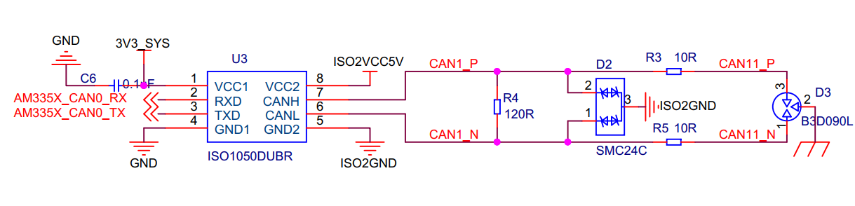
Figure 1 can bus interface block diagram
4 Functional Description
4.1 Functional Block Diagram

Figure 2 CAN bus connect to IOS1050DUBR CAN TRANSCEIVER
Can bus can0 connect to ISO1050, ISO1050 is a galvanically isolated CAN transceiver that meets or exceeds the specifications of the ISO11898 standard
4.2 Can bus specification
4.2.1 Overview
Can Architechture:
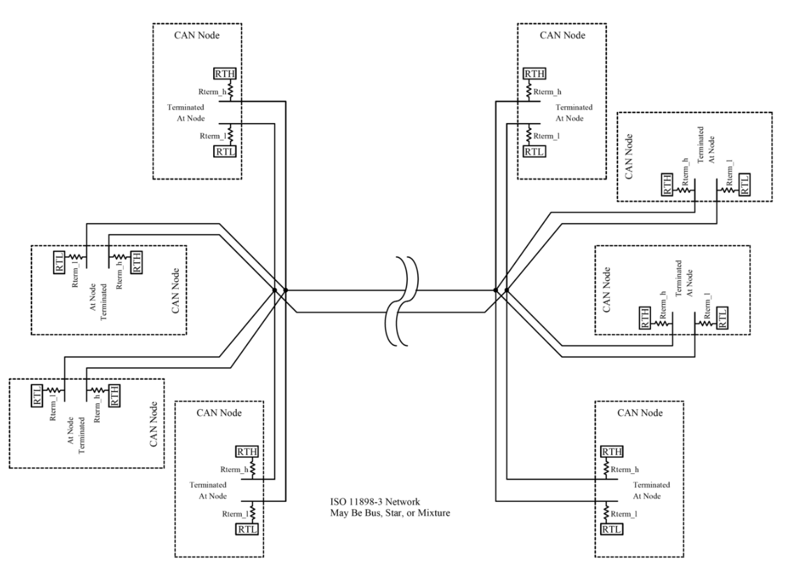
CAN is a multi-master serial bus standard for connecting Electronic Control Units [ECUs] also known as nodes. Two or more nodes are required on the CAN network to communicate. The complexity of the node can range from a simple I/O device up to an embedded computer with a CAN interface and sophisticated software. The node may also be a gateway allowing a standard computer to communicate over a USB or Ethernet port to the devices on a CAN network.
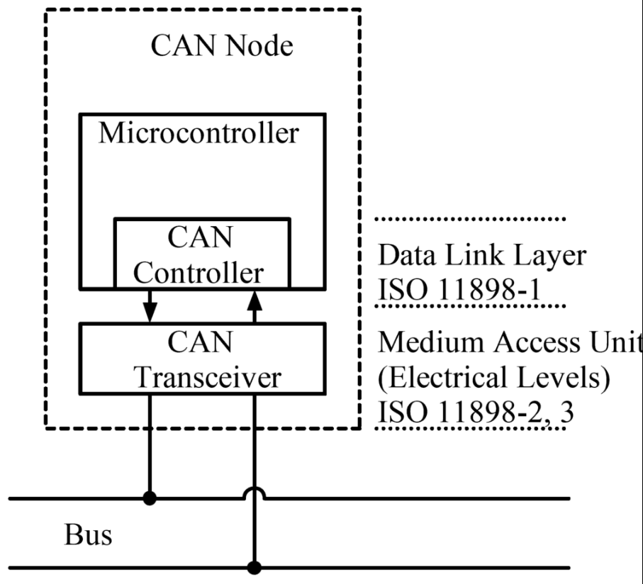
Can Node Architechture:
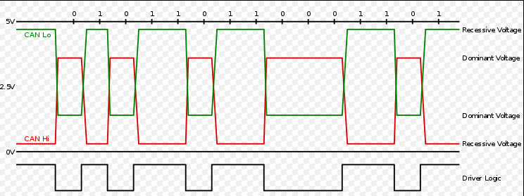
Can bus high speed signal:
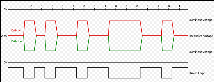
Can bus low speed signal:
4.2.2 Block diagram
Can总线如何仲裁:
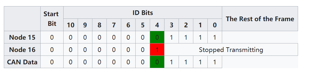
CAN BUS arbitration ,For example, consider an 11-bit ID CAN network, with two nodes with IDs of 15 (binary representation, 00000001111) and 16 (binary representation, 00000010000). If these two nodes transmit at the same time, each will first transmit the start bit then transmit the first six zeros of their ID with no arbitration decision being made.
Can总线的帧格式4种,及扩展格式说明如下
Frames[edit]
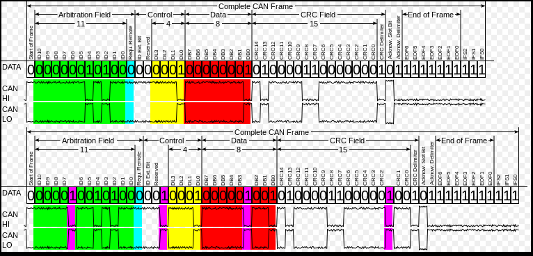
A CAN network can be configured to work with two different message (or "frame") formats: the standard or base frame format (described in CAN 2.0 A and CAN 2.0 B), and the extended frame format (only described by CAN 2.0 B). The only difference between the two formats is that the "CAN base frame" supports a length of 11 bits for the identifier, and the "CAN extended frame" supports a length of 29 bits for the identifier, made up of the 11-bit identifier ("base identifier") and an 18-bit extension ("identifier extension"). The distinction between CAN base frame format and CAN extended frame format is made by using the IDE bit, which is transmitted as dominant in case of an 11-bit frame, and transmitted as recessive in case of a 29-bit frame. CAN controllers that support extended frame format messages are also able to send and receive messages in CAN base frame format. All frames begin with a start-of-frame (SOF) bit that denotes the start of the frame transmission.
CAN has four frame types:
Data frame: a frame containing node data for transmission
Remote frame: a frame requesting the transmission of a specific identifier
Error frame: a frame transmitted by any node detecting an error
Overload frame: a frame to inject a delay between data or remote frame
Data frame[edit]
The data frame is the only frame for actual data transmission. There are two message formats:
Base frame format: with 11 identifier bits
Extended frame format: with 29 identifier bits
The CAN standard requires the implementation must accept the base frame format and may accept the extended frame format, but must tolerate the extended frame format.
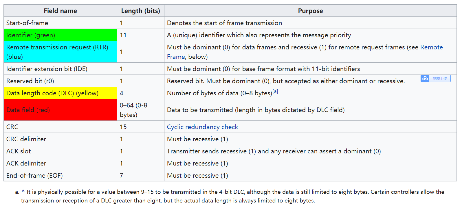
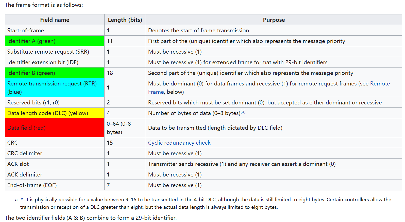
Base frame format
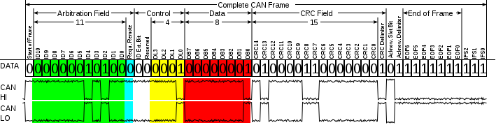
The frame format is as follows: The bit values are described for CAN-LO signal.
Extended frame format[edit]
The frame format is as follows:
The two identifier fields (A & B) combine to form a 29-bit identifier.
Remote frame[edit]
Generally data transmission is performed on an autonomous basis with the data source node (e.g., a sensor) sending out a Data Frame. It is also possible, however, for a destination node to request the data from the source by sending a Remote Frame.
There are two differences between a Data Frame and a Remote Frame. Firstly the RTR-bit is transmitted as a dominant bit in the Data Frame and secondly in the Remote Frame there is no Data Field. The DLC field indicates the data length of the requested message (not the transmitted one)
i.e.,
RTR = 0 ; DOMINANT in data frame
RTR = 1 ; RECESSIVE in remote frame
In the event of a Data Frame and a Remote Frame with the same identifier being transmitted at the same time, the Data Frame wins arbitration due to the dominant RTR bit following the identifier.
Error frame[edit]
The error frame consists of two different fields:
The first field is given by the superposition of ERROR FLAGS (6–12 dominant/recessive bits) contributed from different stations.
The following second field is the ERROR DELIMITER (8 recessive bits).
There are two types of error flags:
Active Error Flag
six dominant bits – Transmitted by a node detecting an error on the network that is in error state "error active".
Passive Error Flag
six recessive bits – Transmitted by a node detecting an active error frame on the network that is in error state "error passive".
There are two error counters in CAN:
1. Transmit error counter (TEC)
2. Receive error counter (REC)
When TEC or REC is greater than 127 and lesser than 255, a Passive Error frame will be transmitted on the bus.
When TEC and REC is lesser than 128, an Active Error frame will be transmitted on the bus.
When TEC is greater than 255, then the node enters into Bus Off state, where no frames will be transmitted.
Overload frame[edit]
The overload frame contains the two bit fields Overload Flag and Overload Delimiter. There are two kinds of overload conditions that can lead to the transmission of an overload flag:
The internal conditions of a receiver, which requires a delay of the next data frame or remote frame.
Detection of a dominant bit during intermission.
The start of an overload frame due to case 1 is only allowed to be started at the first bit time of an expected intermission, whereas overload frames due to case 2 start one bit after detecting the dominant bit. Overload Flag consists of six dominant bits. The overall form corresponds to that of the active error flag. The overload flag’s form destroys the fixed form of the intermission field. As a consequence, all other stations also detect an overload condition and on their part start transmission of an overload flag. Overload Delimiter consists of eight recessive bits. The overload delimiter is of the same form as the error delimiter.
ACK slot[edit]
The acknowledge slot is used to acknowledge the receipt of a valid CAN frame. Each node that receives the frame without finding an error, transmits a dominant level in the ACK slot and thus overrides the recessive level of the transmitter. If a transmitter detects a recessive level in the ACK slot it knows that no receiver found a valid frame. A receiving node may transmit a recessive to indicate that it did not receive a valid frame, but another node that did receive a valid frame may override this with a dominant. The transmitting node cannot know that the message has been received by all of the nodes on the CAN network.
Often, the mode of operation of the device is to re-transmit unacknowledged frames over and over. This may lead to eventually entering the "error passive" state.
Interframe spacing[edit]
Data frames and remote frames are separated from preceding frames by a bit field called interframe space. Interframe space consists of at least three consecutive recessive (1) bits. Following that, if a dominant bit is detected, it will be regarded as the "Start of frame" bit of the next frame. Overload frames and error frames are not preceded by an interframe space and multiple overload frames are not separated by an interframe space. Interframe space contains the bit fields intermission and bus idle, and suspend transmission for error passive stations, which have been transmitter of the previous message.[13]
Can总线上帧消息通过ACK slot进行应答,但是缺点是有可以被其它接收结点覆盖。
ACK slot[edit]
The acknowledge slot is used to acknowledge the receipt of a valid CAN frame. Each node that receives the frame without finding an error, transmits a dominant level in the ACK slot and thus overrides the recessive level of the transmitter. If a transmitter detects a recessive level in the ACK slot it knows that no receiver found a valid frame. A receiving node may transmit a recessive to indicate that it did not receive a valid frame, but another node that did receive a valid frame may override this with a dominant. The transmitting node cannot know that the message has been received by all of the nodes on the CAN network.
Often, the mode of operation of the device is to re-transmit unacknowledged frames over and over. This may lead to eventually entering the "error passive" state.
Can总线如何区分不同的帧消息:通过在总线上结束帧后面发送连续的至少3个隐性位1.
Interframe spacing[edit]
Data frames and remote frames are separated from preceding frames by a bit field called interframe space. Interframe space consists of at least three consecutive recessive (1) bits. Following that, if a dominant bit is detected, it will be regarded as the "Start of frame" bit of the next frame. Overload frames and error frames are not preceded by an interframe space and multiple overload frames are not separated by an interframe space. Interframe space contains the bit fields intermission and bus idle, and suspend transmission for error passive stations, which have been transmitter of the previous message.[13]
CAN总线通过位填充来保证同步。
Bit stuffing[edit]
To ensure enough transitions to maintain synchronization, a bit of opposite polarity is inserted after five consecutive bits of the same polarity. This practice is called bit stuffing, and is necessary due to the non-return to zero (NRZ) coding used with CAN. The stuffed data frames are destuffed by the receiver.
All fields in the frame are stuffed with the exception of the CRC delimiter, ACK field and end of frame which are a fixed size and are not stuffed. In the fields where bit stuffing is used, six consecutive bits of the same polarity (111111 or 000000) are considered an error. An active error flag can be transmitted by a node when an error has been detected. The active error flag consists of six consecutive dominant bits and violates the rule of bit stuffing.
Bit stuffing means that data frames may be larger than one would expect by simply enumerating the bits shown in the tables above. The maximum increase in size of a CAN frame (base format) after bit stuffing is in the case
11111000011110000...
which is stuffed as (stuffing bits in bold):
111110000011111000001...
The stuffing bit itself may be the first of the five consecutive identical bits, so in the worst case there is one stuffing bit per four original bits.
The size is bounded by
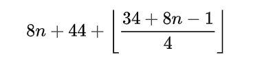
in the worst case one bit will be added every four original bits after the first one (hence the −1 at the numerator) and, because of the layout of the bits of the header, only 34 out of 44 of them can be subject to bit stuffing.
An undesirable side effect of the bit stuffing scheme is that a small number of bit errors in a received message may corrupt the destuffing process, causing a larger number of errors to propagate through the destuffed message. This reduces the level of protection that would otherwise be offered by the CRC against the original errors. This deficiency of the protocol has been addressed in CAN FD frames by the use of a combination of fixed stuff bits and a counter that records the number of stuff bits inserted.
5 Interface
5.1 Driver 4.14.40
Dts file modify:
Index: arch/arm/boot/dts/am335x-evm.dts
dcan0_pins_default: dcan0_pins_default {
pinctrl-single,pins = <
AM33XX_IOPAD(0x978, PIN_OUTPUT | MUX_MODE2) /* uart1_ctsn.d_can0_tx */
AM33XX_IOPAD(0x97c, PIN_INPUT_PULLDOWN | MUX_MODE2) /* uart1_rtsn.d_can0_rx */
>;
};
};
&dcan0 {
status = "okay"; /* Enable only if Profile 1 is selected */
pinctrl-names = "default";
pinctrl-0 = <&dcan0_pins_default>;
};
kernel config
# CONFIG_NET_PKTGEN is not set
# CONFIG_HAMRADIO is not set
+CONFIG_CAN=y
+CONFIG_CAN_RAW=y
+CONFIG_CAN_BCM=y
+CONFIG_CAN_GW=y
#
# CAN Device Drivers
@@ -1172,20 +1172,20 @@
# CONFIG_CAN_VCAN is not set
# CONFIG_CAN_VXCAN is not set
# CONFIG_CAN_SLCAN is not set
+CONFIG_CAN_DEV=y
CONFIG_CAN_CALC_BITTIMING=y
# CONFIG_CAN_LEDS is not set
# CONFIG_CAN_FLEXCAN is not set
# CONFIG_CAN_GRCAN is not set
# CONFIG_CAN_TI_HECC is not set
+CONFIG_CAN_C_CAN=y
+CONFIG_CAN_C_CAN_PLATFORM=y
# CONFIG_CAN_C_CAN_PCI is not set
# CONFIG_CAN_CC770 is not set
# CONFIG_CAN_IFI_CANFD is not set
+CONFIG_CAN_M_CAN=y
# CONFIG_CAN_PEAK_PCIEFD is not set
+CONFIG_CAN_RCAR=y
# CONFIG_CAN_RCAR_CANFD is not set
# CONFIG_CAN_SJA1000 is not set
# CONFIG_CAN_SOFTING is not set
kerenl print info
[ 1.090016] c_can_platform 481cc000.can: c_can_platform device registered (regs=fa1cc000, irq=37)
[ 1.431054] can: controller area network core (rev 20170425 abi 9)
[ 1.441954] can: raw protocol (rev 20170425)
[ 1.446329] can: broadcast manager protocol (rev 20170425 t)
[ 1.452066] can: netlink gateway (rev 20170425) max_hops=1
root@am335x-evm:~# cat /proc/net/dev
Inter-| Receive | Transmit
face |bytes packets errs drop fifo frame compressed multicast|bytes packets errs drop fifo colls carrier compressed
eth0: 2788 23 0 0 0 0 0 0 3920 35 0 0 0 0 0 0
lo: 18908 248 0 0 0 0 0 0 18908 248 0 0 0 0 0 0
sit0: 0 0 0 0 0 0 0 0 0 0 0 0 0 0 0 0
can0: 0 0 0 0 0 0 0 0 0 0 0 0 0 0 0 0
eth1: 0 0 0 0 0 0 0 0 0 0 0 0 0 0 0 0
5.2 Application Interface
就像TCP/IP协议一样,在使用CAN网络之前你首先需要打开一个套接字。CAN的套接字使用到了一个新的协议族,所以在调用socket(2)这个系统函数的时候需要将PF_CAN作为第一个参数。当前有两个CAN的协议可以选择,一个是原始套接字协议( raw socket protocol),另一个是广播管理协议BCM(broadcast manager)。你可以这样来打开一个套接字:
s
= socket(PF_CAN, SOCK_RAW, CAN_RAW);
或者
s
= socket(PF_CAN, SOCK_DGRAM, CAN_BCM);
在成功创建一个套接字之后,你通常需要使用bind(2)函数将套接字绑定在某个CAN接口上(这和TCP/IP使用不同的IP地址不同,参见第3章)。在绑定 (CAN_RAW)或连接(CAN_BCM)套接字之后,你可以在套接字上使用read(2)/write(2),也可以使用send(2)/sendto(2)/sendmsg(2)和对应的recv*操作。当然也会有CAN特有的套接字选项,下面将会说明。
基本的CAN帧结构体和套接字地址结构体定义在include/linux/can.h:
/*
* 扩展格式识别符由 29 位组成。其格式包含两个部分:11 位基本 ID、18 位扩展 ID。
* Controller Area Network Identifier structure
*
* bit
0-28 : CAN识别符 (11/29 bit)
* bit 29 : 错误帧标志 (0 = data frame, 1 = error
frame)
* bit 30 : 远程发送请求标志 (1 = rtr frame)
* bit
31 :帧格式标志 (0 = standard 11 bit, 1 = extended
29 bit)
*/
typedef __u32 canid_t;
struct can_frame {
canid_t
can_id; /* 32 bit CAN_ID + EFF/RTR/ERR flags */
__u8 can_dlc; /* 数据长度: 0 .. 8 */
__u8 data[8] __attribute__((aligned(8)));
};
结构体的有效数据在data[]数组中,它的字节对齐是64bit的,所以用户可以比较方便的在data[]中传输自己定义的结构体和共用体。CAN总线中没有默认的字节序。在CAN_RAW套接字上调用read(2),返回给用户空间的数据是一个struct can_frame结构体。
就像PF_PACKET套接字一样,sockaddr_can结构体也有接口的索引,这个索引绑定了特定接口:
struct
sockaddr_can {
sa_family_t
can_family;
int can_ifindex;
union {
/* transport protocol class
address info (e.g. ISOTP) */
struct { canid_t rx_id, tx_id; } tp;
/* reserved for future CAN protocols address information */
} can_addr;
};
指定接口索引需要调用ioctl()(比如对于没有错误检查CAN_RAW套接字):
int s;
struct
sockaddr_can addr;
struct ifreq
ifr;
s =
socket(PF_CAN, SOCK_RAW, CAN_RAW);
strcpy(ifr.ifr_name, "can0" );
ioctl(s, SIOCGIFINDEX, &ifr);
addr.can_family = AF_CAN;
addr.can_ifindex = ifr.ifr_ifindex;
bind(s,
(struct sockaddr *)&addr, sizeof(addr));
(..)
为了将套接字和所有的CAN接口绑定,接口索引必须是0。这样套接字便可以从所有使能的CAN接口接收CAN帧。recvfrom(2)可以指定从哪个接口接收。在一个已经和所有CAN接口绑定的套接字上,sendto(2)可以指定从哪个接口发送。
从一个CAN_RAW套接字上读取CAN帧也就是读取struct can_frame结构体:
struct
can_frame frame;
nbytes =
read(s, &frame, sizeof(struct can_frame));
if (nbytes
< 0) {
perror("can raw socket read");
return 1;
}
/* paranoid
check ... */
if (nbytes
< sizeof(struct can_frame)) {
fprintf(stderr, "read: incomplete CAN frame\n");
return 1;
}
/* do
something with the received CAN frame */
写CAN帧也是类似的,需要用到write (2)函数:
nbytes =
write(s, &frame, sizeof(struct can_frame));
如果套接字跟所有的CAN接口都绑定了(addr.can_index = 0),推荐使用recvfrom(2)获取数据源接口的信息:
struct
sockaddr_can addr;
struct ifreq
ifr;
socklen_t
len = sizeof(addr);
struct
can_frame frame;
nbytes =
recvfrom(s, &frame, sizeof(struct can_frame),
0, (struct sockaddr*)&addr, &len);
/* get
interface name of the received CAN frame */
ifr.ifr_ifindex = addr.can_ifindex;
ioctl(s,
SIOCGIFNAME, &ifr);
printf("Received a CAN frame from interface %s", ifr.ifr_name);
对于绑定了所有接口的套接字,向某个端口发送数据必须指定接口的详细信息:
strcpy(ifr.ifr_name, "can0");
ioctl(s,
SIOCGIFINDEX, &ifr);
addr.can_ifindex = ifr.ifr_ifindex;
addr.can_family = AF_CAN;
nbytes =
sendto(s, &frame, sizeof(struct can_frame),
0, (struct sockaddr*)&addr, sizeof(addr));
4.1 使用can_filter的原始套接字 (RAW socket)
----------------------------------------------------
CAN_RAW套接字的用法和CAN字符设备的用法是类似的。为了使用CAN套接字的新特性,在绑定原始套接字的时候将会默认开启以下特性:
- filter将会接收所有的数据
- 套接字仅仅接收有效的数据帧(=> no error frames)
- 发送帧的回环功能被开启(参见 3.2节)
- (回环模式下)套接字不接收它自己发送的帧
这些特性的设置可以在绑定之前和之后修改。为了使用CAN_RAW套接字相关的选项,必须包含<linux/can/raw.h>。
- 4.1.1 原始套接字选项 CAN_RAW_FILTER
CAN_RAW套接字的接收可以使用CAN_RAW_FILTER套接字选项指定的多个过滤规则(过滤器)来过滤。
过滤规则(过滤器)的定义在 include/linux/can.h中:
struct
can_filter {
canid_t can_id;
canid_t can_mask;
};
过滤规则的匹配:
<received_can_id> & mask == can_id & mask
/*
#define CAN_INV_FILTER 0x20000000U
/* to be set in can_filter.can_id */
#define CAN_ERR_FLAG
0x20000000U /* error frame */
*/
这和大家所熟知的CAN控制器硬件过滤非常相似。可以使用 CAN_INV_FILTER这个宏将can_filter结构体的成员can_id中的比特位反转。和CAN控制器的硬件过滤形成鲜明对比的是,用户可以为每一个打开的套接字设置多个独立的过滤规则(过滤器):
/*
/* valid bits in CAN ID for frame
formats */
#define CAN_SFF_MASK 0x000007FFU
/* 标准帧格式 (SFF) */
#define CAN_EFF_MASK 0x1FFFFFFFU /* 扩展帧格式 (EFF) */
#define CAN_ERR_MASK 0x1FFFFFFFU /* 忽略EFF, RTR, ERR标志 */
*/
struct
can_filter rfilter[2];
rfilter[0].can_id = 0x123;
rfilter[0].can_mask = CAN_SFF_MASK;
rfilter[1].can_id = 0x200;
rfilter[1].can_mask = 0x700;
setsockopt(s, SOL_CAN_RAW, CAN_RAW_FILTER, &rfilter, sizeof(rfilter));
为了在指定的CAN_RAW套接字上禁用接收过滤规则,可以这样:
setsockopt(s,
SOL_CAN_RAW, CAN_RAW_FILTER, NULL, 0);
在一些极端情况下不需要读取数据,可以把过滤规则清零(所有成员设为0),这样原始套接字就会忽略接收到的CAN帧。在这种仅仅发送数据(不读取)的应用中可以在内核中省略接收队列,以此减少CPU的负载(虽然只能减少一点点)。
- 原始套接字选项 CAN_RAW_ERR_FILTER
正如3.4节所说,CAN接口驱动可以选择性的产生错误帧,错误帧和正常帧以相同的方式传给应用程序。可能产生的错误被分为不同的种类,使用适当的错误掩码可以过滤它们。为了注册所有可能的错误情况,CAN_ERR_MASK(0x1FFFFFFFU)这个宏可以用来作为错误掩码。这个错误掩码定义在linux/can/error.h。
can_err_mask_t err_mask = ( CAN_ERR_TX_TIMEOUT | CAN_ERR_BUSOFF );
setsockopt(s, SOL_CAN_RAW, CAN_RAW_ERR_FILTER,
&err_mask, sizeof(err_mask));
- 原始套接字选项 CAN_RAW_LOOPBACK
为了满足众多应用程序的需要,本地回环功能默认是开启的(详细情况参考3.2节)。但是在一些嵌入式应用场景中(比如只有一个用户在使用CAN总线),回环功能可以被关闭(各个套接字之间是独立的):
int loopback
= 0; /* 0 = disabled, 1 = enabled (default) */
setsockopt(s, SOL_CAN_RAW, CAN_RAW_LOOPBACK, &loopback, sizeof(loopback));
- 原始套接字选项 CAN_RAW_RECV_OWN_MSGS
在本地回环功能开启的情况下,所有的发送帧都会被回环到在相应CAN接口上注册了同样CAN-ID(和发送帧的相同)的套接字上。发送CAN帧的套接字被假设不想接收自己发送的CAN帧,因此在发送套接字上的回环功能默认是关闭的。可以在需要的时候改变这一默认行为:
int
recv_own_msgs = 1; /* 0 = disabled (default), 1 = enabled */
setsockopt(s, SOL_CAN_RAW, CAN_RAW_RECV_OWN_MSGS,
&recv_own_msgs, sizeof(recv_own_msgs));
6
Example
#include <stdio.h>
#include <string.h>
#include <sys/socket.h>
#include <linux/sockios.h>
#include <linux/if.h>
#include <pthread.h>
#include "can.h"
#define PF_CAN 29
#define AF_CAN PF_CAN
#define SIOCSCANBAUDRATE (SIOCDEVPRIVATE+0)
#define SIOCGCANBAUDRATE (SIOCDEVPRIVATE+1)
#define SOL_CAN_RAW (SOL_CAN_BASE + CAN_RAW)
#define CAN_RAW_FILTER 1
#define CAN_RAW_RECV_OWN_MSGS 0x4
typedef __u32 can_baudrate_t;
struct ifreq ifr;
int init_can(char* can) {
int
sock;
struct
sockaddr_can addr;
//struct
ifreq ifr;
sock =
socket(PF_CAN, SOCK_RAW, CAN_RAW);
if(sock
< 0) {
printf("error\n");
return
-1;
}
addr.can_family
= AF_CAN;
strcpy(ifr.ifr_name,
can );
int
ret;
ret =
ioctl(sock, SIOCGIFINDEX, &ifr);
//get index
if(ret
&& ifr.ifr_ifindex == 0) {
printf("Can't
get interface index for can0, code= %d, can0 ifr_ifindex value: %d, name:
%s\n", ret, ifr.ifr_ifindex, ifr.ifr_name);
close(sock);
return
-1;
}
printf("%s
can_ifindex = %x\n",ifr.ifr_name,ifr.ifr_ifindex);
addr.can_ifindex
= ifr.ifr_ifindex;
//ioctl(sock,SIOCGIFNAME,&ifr);
//printf("ret
= %d can0 can_ifname = %s\n",ret,ifr.ifr_name);
int
recv_own_msgs = 0;//set loop back: 1
enable 0 disable
setsockopt(sock,
SOL_CAN_RAW, CAN_RAW_RECV_OWN_MSGS,&recv_own_msgs, sizeof(recv_own_msgs));
if
(bind(sock,(struct sockaddr*)&addr,sizeof(addr))<0) {
printf("bind
error\n");
close(sock);
return
-1;
}
return
sock;
}
void Can_Read_thread(void* psock)
{
int
sock = *(int *)psock;
int i =
0;
struct
can_frame frame;
while(1)
{
memset(&frame,0,sizeof(struct can_frame));
read(sock,&frame,sizeof(struct
can_frame));
if(frame.can_dlc)
{
printf("\n%s
DLC:%d Data:", ifr.ifr_name, frame.can_dlc);
for(i
= 0; i < frame.can_dlc; i++)
{
printf("%#x
",frame.data[i]);
}
printf("\n");
}
}
}
int Write_Can_Data(int sock,char* str,int len)
{
struct
can_frame frame;
int i;
int
nbytes = 0;
frame.can_id
= 0x0; //can device id
while(len)
{
if(len
> sizeof(frame.data)) {
memset(&frame.data,0,sizeof(frame.data));
memcpy(&frame.data,str,sizeof(frame.data));
//printf("%d,(%s)\r\n",sizeof(frame.data),frame.data);
frame.can_dlc
= sizeof(frame.data);
str
+= sizeof(frame.data);
len
-= sizeof(frame.data);
}
else
{
memset(&frame.data,0,sizeof(frame.data));
memcpy(&frame.data,str,len);
//printf("%d,(%s)\r\n",len,frame.data);
frame.can_dlc
= len;
str
= NULL;
len
= 0;
}
write(sock,
&frame, sizeof(struct can_frame));
usleep(100);
}
}
int main(int argc ,char** argv)
{
int
sock;
int
nbytes;
pthread_t
canthreadid;
int
ret;
char
str[4096];
if(argc
< 2) {
printf("Usage:
%s <device>(can0/can1)\n", argv[0]);
return
0;
}
sock =
init_can(argv[1]);
if(sock
< 0)
{
return
0;
}
ret=pthread_create(&canthreadid,NULL,(void*)Can_Read_thread,&sock);
while(1)
{
printf("Please
Input string to send to %s\n:",argv[1]);
scanf("%s",
str);
if(strlen(str)>0)
Write_Can_Data(sock,str,strlen(str));
}
close(sock);
printf("ok\n");
return
0;
}
am335x system upgrade kernel can(八)的更多相关文章
- am335x system upgrade kernel emmc(十八)
1 Scope of Document This document describes EMMC hardware design 2 Requiremen 2.1 Func ...
- am335x system upgrade kernel tf(五)
1 Scope of Document This document describes TF hardware design 2 Requiremen 2.1 Functi ...
- am335x system upgrade kernel ethernet(四)
1 Scope of Document This document describes ethernet hardware design and porting KZS8081 to ubo ...
- am335x system upgrade kernel gpio(九)
1 Hardware Overview gpio interface,pin map: AM335X_I2C0_W_C----------------------MCASP0_AXR1 /* ...
- am335x system upgrade kernel uart(七)
1 Scope of Document This document describes UART hardware design, uart driver porting 2 Re ...
- am335x system upgrade kernel i2c rtc eeprom(六)
1 Scope of Document This document describes i2c bus hardware design and support i2c-devices: ee ...
- am335x system upgrade kernel ec20 simcom7600ce(十一)
1 Scope of Document This document describes 4G hardware design, support quectel ec20 4G module/ ...
- am335x system upgrade kernel usb stroage(十)
1 Scope of Document This document describes USB hardware design, support stardard usb2.0 port o ...
- am335x system upgrade kernel f-ram fm25l16b(十六)
1 Scope of Document This document describes SPI F-RAM hardware design 2 Requiremen 2.1 ...
随机推荐
- Java代码生成器Easy Code
EasyCode是基于IntelliJ IDEA开发的代码生成插件,支持自定义任意模板(Java,html,js,xml).只要是与数据库相关的代码都可以通过自定义模板来生成.支持数据库类型与java ...
- LOJ3119 CTS2019 随机立方体 概率、容斥、二项式反演
传送门 为了方便我们设\(N\)是\(N,M,L\)中的最小值,某一个位置\((x,y,z)\)所控制的位置为集合\(\{(a,b,c) \mid a = x \text{或} b = y \text ...
- Sql CLR创建一个简单的表值函数
1.创建面目: 2. 添加函数代码: using System; using System.Data.Sql; using Microsoft.SqlServer.Server; using Syst ...
- go 学习笔记(2)go test
Test 的写法: 每一个test文件必须import 一个"testing" test文件下的每一个test case均必须以Test开头并且符合TestXxx形式,否则go t ...
- [高清·非影印]Spring实战+SpringBoot实战+Spring微服务实战+SpringCloud微服务实战(全4本)
------ 郑重声明 --------- 资源来自网络,纯粹共享交流, 如果喜欢,请您务必支持正版!! --------------------------------------------- 下 ...
- EasyARM-iMX283 安装NFS
1. 安装NFS软件包在 ubuntu 上请输入下面命令:[chenxibing@localhost ~]$ sudo apt-get install nfs-kernel-server[chenxi ...
- 【洛谷 P1641】 [SCOI2010]生成字符串(Catalan数)
题目链接 可以看成在坐标系中从\((0,0)\)用\(n+m\)步走到\((n+m,n-m)\)的方案数,只能向右上\((1)\)或者右下\((0)\)走,而且不能走到\(y=-1\)这条直线上. 不 ...
- MySQL5.7.16安装及配置
一.下载 下载页面http://dev.mysql.com/downloads/mysql/ 选择系统平台后,点击download(根据系统选择64或32位) 二.配置 1.下载成功后,解压安装包到要 ...
- android RecyclerView的瀑布流布局案例
1.先创建 activity_water_fall.xml 和 activity_water_fall_item.xml <?xml version="1.0" encodi ...
- iOS进阶之多线程--NSThread详解
NSThread简介 NSThread是苹果官方提供面向对象操作线程的技术,简单方便,可以直接操作线程对象,不过需要自己控制线程的生命周期.在平时使用很少,最常用到的无非就是 [NSThread cu ...