PID控制器(比例-积分-微分控制器)- V
Linear Actuator - PID Control
Introduction
This application guide is designed to explain the basics of PID control and how to implement a basic control loop using Phidgets.
Once implemented, the control loop will allow the linear actuator to move to a precise position and remain there, even if an external force tries to move it.
PID Control Basics
Proportional Control
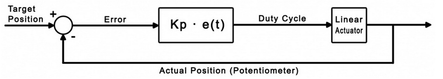
The goal of a control loop is to use data from the feedback device (in this case, the potentiometer) to iteratively adjust the output
until it has reached the target value.
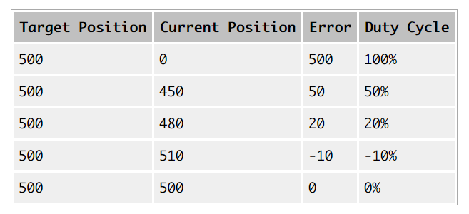
For example, consider this simple control loop (This code would be used in the sensor change event handler):
DutyCycle = TargetPosition - ActualPosition;

if (DutyCycle > )

     DutyCycle = ;

if (DutyCycle < -)

     DutyCycle = -;
Whenever the potentiometer value (ActualPosition) changes, the event handler triggers and updates the Duty Cycle of the motor.
Eventually, this will result in the motor reaching its target. The following table further illustrates how this works:
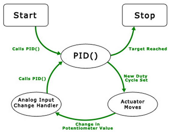
This diagram illustrates the flow of the simple control loop being implemented.
The function PID() is called, which sets a new duty cycle, which causes the actuator to move.
Eight milliseconds later, the potentiometer that keeps track of how far the actuator has extended causes an analog input change event,
which in turn calls PID() again. The cycle continues until the target position is reached.
The type of control we've just implemented here is called Proportional control,
because the output is directly proportional to the error.
We can multiply (TargetPosition - ActualPosition) by a gain value if we want to control how the control loop behaves when it gets close to the target.
A lower value (i.e. less than 1) will result in a more gradual reduction in speed as the actuator reaches its target position,
while a larger value will result in a sharper, quicker response.
We'll call this value the proportional gain, or Kp for short.
If the proportional gain is set too high, the actuator will overshoot the target position and oscillate back and forth around the target.
While we've gained basic control of the actuator position, there are still some problems with purely proportional control.
You may find that the actuator never quite reaches the target position, especially with a low proportional gain.
Also, if the load on the actuator changes while it's moving, it won't be able to react to the difference.
To solve these problems, we need an integral term.
Integral Control
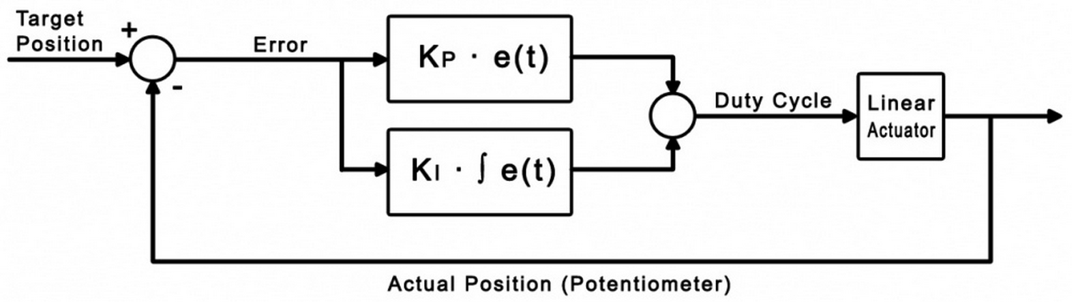
The purpose of the integral term in a control loop is to look back at all of the past error
and accumulate it into an offset that the control loop can use.
Combined with our proportional control loop, it will be able to react to changes in load and land closer
to the target position if we choose our gain values properly.
dt = 0.008;

error = TargetPosition - ActualPosition;

DutyCycle = (Kp * error) + (Ki * integral);

if (DutyCycle > )

     DutyCycle = ;

else if (DutyCycle < -)

     DutyCycle = -;

else

     integral += (error * dt);
Where dt is the change in time between iterations of the control loop.
For this example, dt is set to 0.008 seconds, which is the update rate of the analog input.
The integral is only accumulated when the duty cycle isn't saturated at 100% or -100%.
This prevents the control loop from needlessly accumulating the integral when it's already running at maximum velocity.
Now we have two control gains: Kp and Ki.
Kp still functions as it did in the proportional example, and Ki controls how influential the integral term is.
Increasing the integral gain will cause the control loop to reach the target faster,
and ensure that you hit the exact target rather than settling to a value close to the target.
Just like the proportional gain, increasing the integral gain too much can cause instability.
After tweaking the control gains, you may find that PI control is sufficient for your application.
If you're having trouble finding control gains that provide the results you're looking for, y
ou can implement full PID control by adding the derivative term.
Derivative Control
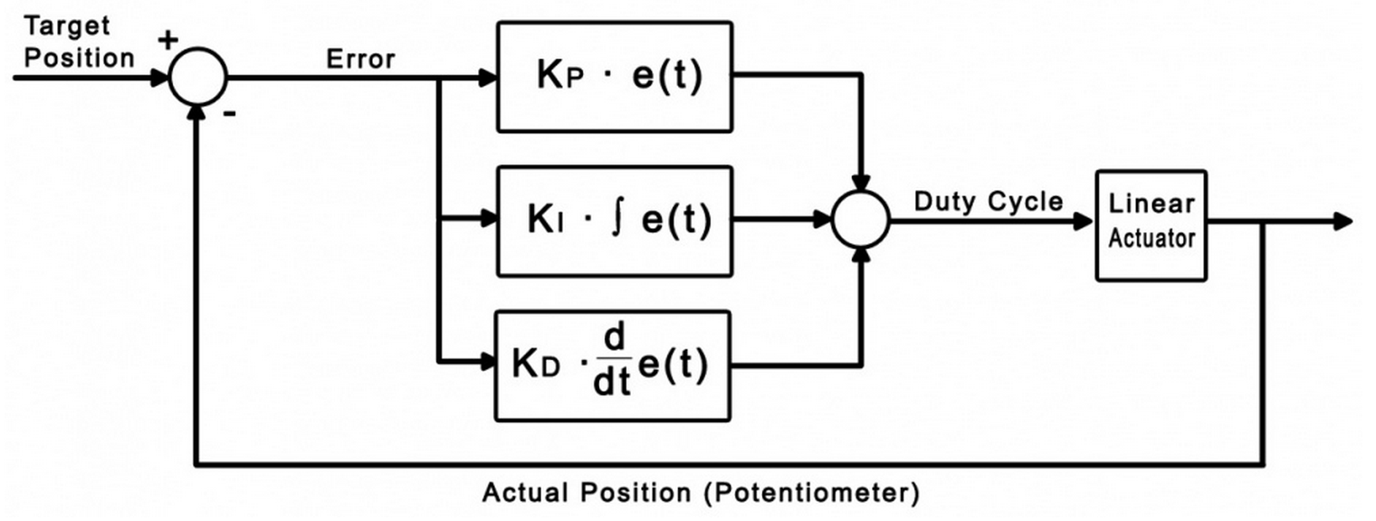
Derivative control looks at past errors in the system and calculates the slope of those errors to predict future error values.
Adding derivative control should add stability to the system and increase the control we have over it by adding another gain value.
dt = 0.008;

error = TargetPosition - ActualPosition;

DutyCycle = (Kp * error) + (Ki * integral) + (Kd * derivative);

if (DutyCycle > )

     DutyCycle = ;

else if (DutyCycle < -)

     DutyCycle = -;

else

     integral += (error * dt);

derivative = (error - errorlast)/dt;
Where errorlast is the error value a set number of samples ago.
In an application such as this, an error value from around 64 samples ago (0.5 seconds) should suffice.
Just as before, we can now use Kd to modify the weight of this new derivative term.
Increasing Kd should smooth things out and increase stability,
but you'll find that it should be kept small in comparison to the other control gains
or it will cause the control to oscillate when it's near the target.
Sample Program
You can download the sample program written for this guide via the link below. This is a Visual C# project.
Controls and Settings
- These boxes contain the information of the attached motor controller. If these boxes are blank, it means the controller object didn't successfully attach.
- These boxes control which motor output and analog input are being used, and allow you to set each of the control gains. You can click on the "?" icon in the top right for more information on a particular setting. Changes will not take effect until the "Start" button is hit.
- These boxes display the target position set by the slider and the actual position according to the feedback potentiometer. The error is the difference between these two values, and the output velocity is the duty cycle of the controller as dictated by the control loop.
- The maximum velocity slider controls the maximum duty cycle that the controller will output. It is unrestricted (100%) by default.
- This slider selects the target position, from 1 to 1000 sensorvalue of the feedback potentiometer.
- Pressing the start button will initiate the control loop and the actuator will begin to move toward the target position. If the actuator does not move, check your power and connections.
- These settings are for actuators whose potentiometers don't span the full range of 0-5V (0 - 1000 sensorvalue). Experiment with your actuator to discover the potentiometer's limits.
- This graph will plot the motor's position and the target position over time.
Algorithm
The PID control algorithm in this sample program operates by setting up a change handler for the analog input connected
to the feedback potentiometer that calls an external function.
This function computes the PID control loop output as briefly described in the previous section.
By changing the output, the motor's duty cycle is set and the function will be called again the next time the sensor change handler triggers
(in 0.008 seconds, because the sampling period of an analog input is 8ms).
This loop will continue until the output of the control loop is zero, at which point the sensor change event will no longer trigger.
// This is the event handler for the attached feedback sensor

void actuator_SensorUpdate(object sender, SensorUpdateEventArgs e)

{

    // If the selected sensor input is the one that triggered this handler,

    if ((e.Index ==  && analogCmb.Text == "") || (e.Index ==  && analogCmb.Text == ""))

    {

        //Store sensor value in global variable

        feedback = e.Value;

        //Run the PID loop

        if (started)

        {

            PID();

        }

        //Update the motor controller with the new duty cycle

        actuator.motors[Convert.ToInt32(motorCmb.Text)].Velocity = Math.Round(output);

    }

}
It's always a good idea to keep your event handlers as small and optimized as possible to avoid missing events.
In this sample program, all of the complexity of the PID algorithm is tucked away in the function "PID( )".
The PID() function:
- Updates error variables
- Checks to see if the actuator has reached its target (and if it has, stops the loop)
- Updates the the output (duty cycle) of the control loop
- Limits the duty cycle to the specified output limit
- Updates the derivative variable
In the downloadable example, this function also updates the graph and all of the text boxes that track the variables.
These lines were removed from the excerpt below for increased readability.
// This function does the control system calculations and sets output to the duty cycle that the motor needs to run at.

void PID()

{

    // Calculate how far we are from the target

    errorlast = error;

    error = input - feedback;

    // If the error is within the specified deadband, and the motor is moving slowly enough,

    // Or if the motor's target is a physical limit and that limit is hit (within deadband margins),

    if ((Math.Abs(error) <= deadBand && Math.Abs(output) < )

        || (input < (deadBand +  + (double)svMinTxt.Value) && feedback < (deadBand +  + (double)svMinTxt.Value))

        || (input > ((double)svMaxTxt.Value - ( + deadBand)) && feedback > ((double)svMaxTxt.Value - ( + deadBand))))

    {

        // Stop the motor

        output = ;

        error = ;

    }

    else

    {

        // Else, update motor duty cycle with the newest output value

        // This equation is a simple PID control loop

        output = ((Kp * error) + (Ki * integral)) + (Kd * derivative);

        errorTxt.Text = error.ToString();

    }

    //Prevent output value from exceeding maximum output specified by user, otherwise accumulate the integral

    if (output >= maxOutput)

        output = maxOutput;

    else if (output <= -maxOutput)

        output = -maxOutput;

    else

        integral += (error * dt);

    derivative = (error - errorlast) / dt;

}
PID控制器(比例-积分-微分控制器)- V的更多相关文章
- PID控制器(比例-积分-微分控制器)- I
形象解释PID算法 小明接到这样一个任务: 有一个水缸点漏水(而且漏水的速度还不一定固定不变),要求水面高度维持在某个位置,一旦发现水面高度低于要求位置,就要往水缸里加水. 小明接到任务后就一直守在水 ...
- PID控制器(比例-积分-微分控制器)- IV
调节/测量放大电路电路图:PID控制电路图 如图是PlD控制电路,即比例(P).积分(I).微分(D)控制电路. A1构成的比例电路与环路增益有关,调节RP1,可使反相器的增益在0·5一∞范围内变化; ...
- PID控制器(比例-积分-微分控制器)- II
Table of Contents Practical Process Control Proven Methods and Best Practices for Automatic PID Cont ...
- PID控制器(比例-积分-微分控制器)- III
PID Controller Algorithms Controller manufacturers arrange the Proportional, Integral and Derivative ...
- [Fundamental of Power Electronics]-PART II-9. 控制器设计-9.5 控制器的设计
9.5 控制器设计 现在让我们来考虑如何设计控制器系统,来满足有关抑制扰动,瞬态响应以及稳定性的规范或者说设计目标.典型的直流控制器设计可以用以下规范定义: 1.负载电流变化对输出电压调节的影响.当负 ...
- .NET/ASP.NET MVC Controller 控制器(深入解析控制器运行原理)
阅读目录: 1.开篇介绍 2.ASP.NETMVC Controller 控制器的入口(Controller的执行流程) 3.ASP.NETMVC Controller 控制器的入口(Controll ...
- 创建控制器的方法、控制器加载view过程、控制器view的生命周期、多控制器组合
在介绍四大对象的那篇博客中,可以基本了解到程序启动的过程: main-->UIApplicationMain-->创建UIApplication的实例和app代理AppDelegate的实 ...
- 集合视图控制器(CollectionViewController) 、 标签控制器(TabBarController) 、 高级控件介绍
1 创建集合视图,设置相关属性以满足要求 1.1 问题 集合视图控制器UIConllectionViewController是一个展示大量数据的控制器,系统默认管理着一个集合视图UICollectio ...
- 【iOS开发-21】UINavigationController导航控制器初始化,导航控制器栈的push和pop跳转理解
(1)导航控制器初始化的时候一般都有一个根视图控制器,导航控制器相当于一个栈,里面装的是视图控制器,最先进去的在最以下,最后进去的在最上面.在最上面的那个视图控制器的视图就是这个导航控制器对外展示的界 ...
随机推荐
- Android 自定义View二(深入了解自定义属性attrs.xml)
1.为什么要自定义属性 要使用属性,首先这个属性应该存在,所以如果我们要使用自己的属性,必须要先把他定义出来才能使用.但我们平时在写布局文件的时候好像没有自己定义属性,但我们照样可以用很多属性,这是为 ...
- python+selenium十三:破解简单的图形验证码
此方法可破解简单的验证码,如: 注:中文识别正在寻找办法 安装: 1.python3 2.Pillow 3.pytesseract 4.tesseract-ocr 下载地址:https://pa ...
- 胖哈勃杯Pwn400、Pwn500详解
概述 这次的胖哈博杯我出了Pwn400.Pwn500两道题目,这里讲一下出题和解题的思路.我个人感觉前两年的Pwn题更多的是考察单一的利用技巧,比我这有个洞怎么利用它拿到权限.但是我研究了一些最近的题 ...
- 2018-2019-2 网络对抗week1 Kali安装 20165333陈国超
Kali安装 安装过程是按照网上的教程装的,链接点击[https://blog.csdn.net/KNIGH_YUN/article/details/79949512] 安装成功的截图 主要说一下安装 ...
- DailyWallpaper v1.03 released
根据这一段时间的使用发现了一些问题,重新修正一下. 修正电脑从休眠状态中恢复时如果没有网络连接程序报错的bug. 添加了异常处理语句,防止抓取网页数据时的错误. 这个版本将是最后一个bug fix版本 ...
- huffman编解码英文文本[Python]
对英文文本的字母进行huffman编码,heapq优先队列构建huffman树 python huffman.py source.txt result.txt import sys import he ...
- jquery数组(sort() 排序)
HTML: <h3>字符串数组排序前</h3> <div id="show5"></div> <h3>排序后</h ...
- Python 导入requests报错No module named requests
刚开始是在Pycharm里面,发现就是不对,导入老提示No module named requests这个错误.后面发现是指向的python.exe路径不对,到setting里面设置换一下路径就好.
- copy 深浅复制
- 《Gradle权威指南》--Gradle插件
No1: 应用插件 apply plugin:'java' apply plugin:org.gradle.api.plugins.JavaPlugin apply plugin:JavaPlugin ...