NAT及静态转换,动态转换及PAT
NAT及静态转换,动态转换及PAT
1 案例1:配置静态NAT
1.1 问题
随着接入Internet的计算机数量的不断猛增,IP地址资源也就愈加显得捉襟见肘。事实上,除了中国教育和科研计算机网(CERNET)外,一般用户几乎申请不到整段的C类IP地址。在其他ISP那里,即使是拥有几百台计算机的大型局域网用户,当他们申请IP地址时,所分配的地址也不过只有几个或十几个IP地址。显然,这样少的IP地址根本无法满足网络用户的需求。
- 在R1上配置静态NAT使192.168.1.1转换为61.159.62.131,192.168.1.2转换为61.159.62.132,实现外部网络访问。
1.2 方案
借助于NAT,私有(保留)地址的"内部"网络通过路由器发送数据包时,私有地址被转换成合法的IP地址,一个局域网只需使用少量IP地址(甚至是1个)即可实现私有地址网络内所有计算机与Internet的通信需求。
这种通过使用少量的公有IP 地址代表较多的私有IP 地址的方式,将有助于减缓可用IP地址空间的枯竭。而且还能够有效地避免来自网络外部的攻击,隐藏并保护网络内部的计算机。
网络拓扑如图-1所示:
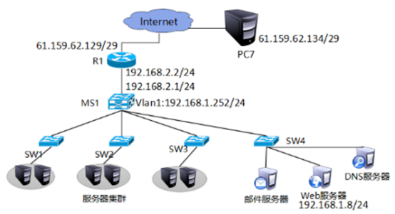
图-1
1.3 步骤
实现此案例需要按照如下步骤进行。
步骤一:通用配置
1)配置R1端口IP地址,以及默认路由
- tarena-R1(config)#interface f0/0
- tarena-R1(config-if)#ip address 192.168.1.254 255.255.255.0
- tarena-R1(config-if)#no shutdown
- tarena-R1(config-if)#interface f0/1
- tarena-R1(config-if)#ip address 61.159.62.129 255.255.255.248
- tarena-R1(config-if)#no shutdown
- tarena-R1(config-if)#exit
- tarena-R1(config)#ip route 0.0.0.0 0.0.0.0 f0/1
2)配置R2端口IP地址
不需要在R2上配置到企业内网的静态路由,因为NAT的存在,企业内部的地址都将被转换、隐藏。
- tarena-R2(config)#interface f0/0
- tarena-R2(config-if)#ip address 61.159.62.130 255.255.255.248
- tarena-R2(config-if)#no shutdown
- tarena-R2(config-if)#interface f0/1
- tarena-R2(config-if)#ip address 192.168.2.254 255.255.255.0
- tarena-R2(config-if)#no shutdown
步骤二:静态NAT配置
1)在R1上将192.168.1.1映射到61.159.62.131,将192.168.1.2映射到61.159.62.132
静态映射有唯一对应的关系。
通过静态NAT,可以把内网服务器发布到外网。
- tarena-R1(config)#ip nat inside source static 192.168.1.1 61.159.62.131
- tarena-R1(config)#ip nat inside source static 192.168.1.2 61.159.62.132
2)在R1上配置NAT内、外端口
- tarena-R1(config)#interface f0/0
- tarena-R1(config-if)#ip nat inside
- tarena-R1(config-if)#interface f0/1
- tarena-R1(config-if)#ip nat outside
3)分别在两台PC机上测试到外网主机的通信
PC1测试如下所示:
- PC>ipconfig
- FastEthernet0 Connection:(default port)
- Link-local IPv6 Address.........: FE80::2D0:FFFF:FE45:CACC
- IP Address......................: 192.168.1.1
- Subnet Mask.....................: 255.255.255.0
- Default Gateway.................: 192.168.1.254
- PC>ping 192.168.2.1
- Pinging 192.168.2.1 with 32 bytes of data:
- Reply from 192.168.2.1: bytes=32 time=1ms TTL=126
- Reply from 192.168.2.1: bytes=32 time=0ms TTL=126
- Reply from 192.168.2.1: bytes=32 time=0ms TTL=126
- Reply from 192.168.2.1: bytes=32 time=0ms TTL=126
- Ping statistics for 192.168.2.1:
- Packets: Sent = 4, Received = 4, Lost = 0 (0% loss),
- Approximate round trip times in milli-seconds:
- Minimum = 0ms, Maximum = 1ms, Average = 0ms
- PC>
PC2的测试如下所示:
- PC>ipconfig
- FastEthernet0 Connection:(default port)
- Link-local IPv6 Address.........: FE80::200:CFF:FEEA:DE30
- IP Address......................: 192.168.1.2
- Subnet Mask.....................: 255.255.255.0
- Default Gateway.................: 192.168.1.254
- PC>ping 192.168.2.1
- Pinging 192.168.2.1 with 32 bytes of data:
- Request timed out.
- Reply from 192.168.2.1: bytes=32 time=0ms TTL=126
- Reply from 192.168.2.1: bytes=32 time=0ms TTL=126
- Reply from 192.168.2.1: bytes=32 time=0ms TTL=126
- Ping statistics for 192.168.2.1:
- Packets: Sent = 4, Received = 3, Lost = 1 (25% loss),
- Approximate round trip times in milli-seconds:
- Minimum = 0ms, Maximum = 0ms, Average = 0ms
- PC>
4)在R1上查看NAT转换表
- tarena-R1#show ip nat translations
- Pro Inside global Inside local Outside local Outside global
- icmp 61.159.62.131:10 192.168.1.1:10 192.168.2.1:10 192.168.2.1:10
- icmp 61.159.62.131:11 192.168.1.1:11 192.168.2.1:11 192.168.2.1:11
- icmp 61.159.62.131:12 192.168.1.1:12 192.168.2.1:12 192.168.2.1:12
- icmp 61.159.62.131:9 192.168.1.1:9 192.168.2.1:9 192.168.2.1:9
- icmp 61.159.62.132:27 192.168.1.2:27 192.168.2.1:27 192.168.2.1:27
- icmp 61.159.62.132:28 192.168.1.2:28 192.168.2.1:28 192.168.2.1:28
- icmp 61.159.62.132:29 192.168.1.2:29 192.168.2.1:29 192.168.2.1:29
- icmp 61.159.62.132:30 192.168.1.2:30 192.168.2.1:30 192.168.2.1:30
2 案例2:配置端口映射
2.1 问题
通过端口映射技术将内部服务器发布向Internet。
2.2 方案
在R1上配置端口映射将192.168.1.3的80端口映射为61.159.62.133的80端口,将web服务器发布到Internet。网络拓扑如图-2所
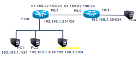
图-2
2.3 步骤
实现此案例需要按照如下步骤进行。
步骤一:通用配置
1)在案例一基础上取消静态转换条目,在192.168.1.0网络新增一台web服务器IP为192.168.1.3。将192.168.1.3的80端口映射为61.159.62.133的80端口
- tarena-R1(config)#no ip nat inside source static 192.168.1.1 61.159.62.131
- tarena-R1(config)#no ip nat inside source static 192.168.1.2 61.159.62.132
- tarena-R1 (config)#ip nat inside source static tcp 192.168.1.3 80 61.159.62.133 80
步骤二:PC3上访问web服务器进行验证
1)外部主机PC4上访问61.159.62.133进行验证,如图-3所示
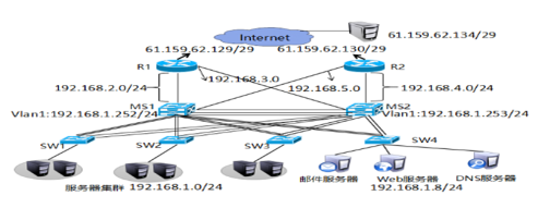
图-3
3 案例3:配置动态NAT
3.1 问题
- 在R1通过动态NAT实现企业内网192.168.1.0/24转换为公网地址61.159.62.131-61.159.62.134,访问192.168.2.1
3.2 方案
网络拓扑如图-4所示:
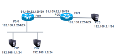
图-4
3.3 步骤
实现此案例需要按照如下步骤进行。
步骤一:动态NAT配置
1)删除案例2中的端口映射
- tarena-R1 (config)#no ip nat inside source static tcp 192.168.1.3 80 61.159.62.133 80
2)在R1上配置ACL
- tarena-R1(config)#access-list 1 permit 192.168.1.0 0.0.0.255
3)在R1上配置可转换的公网IP地址池
地址池是向ISP(Internet服务提供商,如电信、联通)申请得到的,内网主机(上一步ACL中所包含的IP地址)到外网的访问,内网地址将被动态的、随机的转换为这些合法地址。
- tarena-R1(config)#ip nat pool natpool 61.159.62.131 61.159.62.134 netmask 255.255.255.248
4)关联ACL和公网的IP地址池
- tarena-R1(config)#ip nat inside source list 1 pool natpool
5)在R1上配置NAT内、外端口
- tarena-R1(config)#interface f0/0
- tarena-R1(config-if)#ip nat inside
- tarena-R1(config-if)#interface f0/1
- tarena-R1(config-if)#ip nat outside
6)分别在两台PC机上测试到外网主机的通信
PC1测试如下所示:
- PC>ipconfig
- FastEthernet0 Connection:(default port)
- Link-local IPv6 Address.........: FE80::2D0:FFFF:FE45:CACC
- IP Address......................: 192.168.1.1
- Subnet Mask.....................: 255.255.255.0
- Default Gateway.................: 192.168.1.254
- PC>ping 192.168.2.1
- Pinging 192.168.2.1 with 32 bytes of data:
- Reply from 192.168.2.1: bytes=32 time=1ms TTL=126
- Reply from 192.168.2.1: bytes=32 time=0ms TTL=126
- Reply from 192.168.2.1: bytes=32 time=0ms TTL=126
- Reply from 192.168.2.1: bytes=32 time=0ms TTL=126
- Ping statistics for 192.168.2.1:
- Packets: Sent = 4, Received = 4, Lost = 0 (0% loss),
- Approximate round trip times in milli-seconds:
- Minimum = 0ms, Maximum = 1ms, Average = 0ms
- PC>
PC2测试如下所示:
- PC>ipconfig
- FastEthernet0 Connection:(default port)
- Link-local IPv6 Address.........: FE80::2D0:FFFF:FE45:CACC
- IP Address......................: 192.168.1.2
- Subnet Mask.....................: 255.255.255.0
- Default Gateway.................: 192.168.1.254
- PC>ping 192.168.2.1
- Pinging 192.168.2.1 with 32 bytes of data:
- Reply from 192.168.2.1: bytes=32 time=1ms TTL=126
- Reply from 192.168.2.1: bytes=32 time=0ms TTL=126
- Reply from 192.168.2.1: bytes=32 time=0ms TTL=126
- Reply from 192.168.2.1: bytes=32 time=0ms TTL=126
- Ping statistics for 192.168.2.1:
- Packets: Sent = 4, Received = 4, Lost = 0 (0% loss),
- Approximate round trip times in milli-seconds:
- Minimum = 0ms, Maximum = 1ms, Average = 0ms
7)在R1上查看NAT转换表
转换表中的对应关系是动态的,如192.168.1.1被转换为61.159.62.131,但是下一次对外网的访问很有可能被转换为其他地址。
- tarena-R1#show ip nat translations
- Pro Inside global Inside local Outside local Outside global
- icmp 61.159.62.131:1362192.168.1.1:1362 192.168.2.1:1362 192.168.2.1:1362
- icmp 61.159.62.131:1392192.168.1.1:1392 192.168.2.1:1392 192.168.2.1:1392
- icmp 61.159.62.131:1393192.168.1.1:1393 192.168.2.1:1393 192.168.2.1:1393
- icmp 61.159.62.131:1394192.168.1.1:1394 192.168.2.1:1394 192.168.2.1:1394
- icmp 61.159.62.132:13 192.168.1.2:13 192.168.2.1:13 192.168.2.1:13
- icmp 61.159.62.132:14 192.168.1.2:14 192.168.2.1:14 192.168.2.1:14
- icmp 61.159.62.132:15 192.168.1.2:15 192.168.2.1:15 192.168.2.1:15
- icmp 61.159.62.132:16 192.168.1.2:16 192.168.2.1:16 192.168.2.1:16
4 案例4:PAT配置
4.1 问题
在R1配置PAT端口多路复用使企业内网192.168.1.0/24复用f0/1端口的IP,实现外部网络的访问。
4.2 方案
网络拓扑如图-5所示:
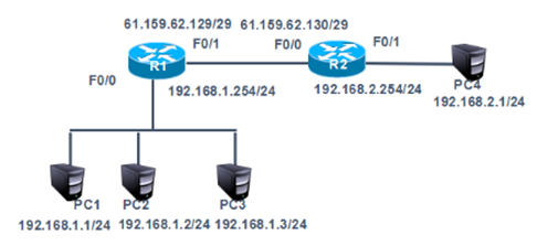
图-5
4.3 步骤
实现此案例需要按照如下步骤进行。
步骤一:基于端口的PAT配置限制
1)删除案例3中动态NAT配置
- tarena-R1(config)#no ip nat inside source list 1
- tarena-R1(config)#no ip nat pool natpool
- tarena-R1(config)#no access-list 1
2)在R1上配置ACL
- tarena-R1(config)#access-list 1 permit 192.168.1.0 0.0.0.255
3)关联ACL和路由器连接互联网的端口
该命令最后加上的overload表示复用。
- tarena-R1(config)#ip nat inside source list 1 interface f0/1 overload
4)在R1上配置NAT内、外端口
- tarena-R1(config)#interface f0/0
- tarena-R1(config-if)#ip nat inside
- tarena-R1(config-if)#interface f0/1
- tarena-R1(config-if)#ip nat outside
5)分别在两台PC机上测试到外网主机的通信
PC1测试如下所示:
- PC>ipconfig
- FastEthernet0 Connection:(default port)
- Link-local IPv6 Address.........: FE80::2D0:FFFF:FE45:CACC
- IP Address......................: 192.168.1.1
- Subnet Mask.....................: 255.255.255.0
- Default Gateway.................: 192.168.1.254
- PC>ping 192.168.2.1
- Pinging 192.168.2.1 with 32 bytes of data:
- Reply from 192.168.2.1: bytes=32 time=1ms TTL=126
- Reply from 192.168.2.1: bytes=32 time=0ms TTL=126
- Reply from 192.168.2.1: bytes=32 time=0ms TTL=126
- Reply from 192.168.2.1: bytes=32 time=0ms TTL=126
- Ping statistics for 192.168.2.1:
- Packets: Sent = 4, Received = 4, Lost = 0 (0% loss),
- Approximate round trip times in milli-seconds:
- Minimum = 0ms, Maximum = 1ms, Average = 0ms
- PC>
PC2测试如下所示:
- PC>ipconfig
- FastEthernet0 Connection:(default port)
- Link-local IPv6 Address.........: FE80::2D0:FFFF:FE45:CACC
- IP Address......................: 192.168.1.2
- Subnet Mask.....................: 255.255.255.0
- Default Gateway.................: 192.168.1.254
- PC>ping 192.168.2.1
- Pinging 192.168.2.1 with 32 bytes of data:
- Reply from 192.168.2.1: bytes=32 time=1ms TTL=126
- Reply from 192.168.2.1: bytes=32 time=0ms TTL=126
- Reply from 192.168.2.1: bytes=32 time=0ms TTL=126
- Reply from 192.168.2.1: bytes=32 time=0ms TTL=126
- Ping statistics for 192.168.2.1:
- Packets: Sent = 4, Received = 4, Lost = 0 (0% loss),
- Approximate round trip times in milli-seconds:
- Minimum = 0ms, Maximum = 1ms, Average = 0ms
- PC>
6)在R1上查看NAT转换表
- tarena-R1#show ip nat translations
- Pro Inside global Inside local Outside local Outside global
- icmp 61.159.62.129:2029192.168.1.1:2029 192.168.2.1:2029 192.168.2.1:2029
- icmp 61.159.62.129:2030192.168.1.1:2030 192.168.2.1:2030 192.168.2.1:2030
- icmp 61.159.62.129:2031192.168.1.1:2031 192.168.2.1:2031 192.168.2.1:2031
- icmp 61.159.62.129:2032192.168.1.1:2032 192.168.2.1:2032 192.168.2.1:2032
- icmp 61.159.62.129:2033192.168.1.1:2033 192.168.2.1:2033 192.168.2.1:2033
- icmp 61.159.62.129:2034192.168.1.1:2034 192.168.2.1:2034 192.168.2.1:2034
- icmp 61.159.62.129:2035192.168.1.1:2035 192.168.2.1:2035 192.168.2.1:2035
输出结果显示,所有的内网IP地址在访问外网前均被转换成了路由器端口的IP地址。
5 案例5:办公区Internet的访问
5.1 问题
在R1配置PAT端口多路复用使企业内网192.168.1.0/24复用f0/1端口的IP,实现外部网络的访问。
5.2 方案
网络拓扑如图-6所示:
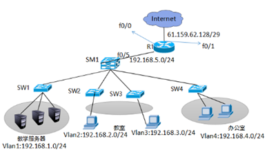
图-6
5.3 步骤
实现此案例需要按照如下步骤进行。
步骤一:在SM1划分vlan2、vlan3、vlan4 并给SM1配置虚端口IP并开启路由功能,1-4接口开启trunk
1)创建vlan并设置管理IP,开启路由功能,并把相应的接口划分到vlan下
- SM1 (config)ip routing
- SM1 (config)#vlan 2
- SM1 (config-vlan)#vlan 3
- SM1 (config-vlan)#vlan 4
- SM1 (config-vlan)#
- SM1 (config-vlan)#exit
- SM1 (config)#interface vlan 1
- SM1 (config-if)#ip address 192.168.1.254 255.255.255.0
- SM1 (config-if)#eixt
- SM1 (config-if)#no shutdown
- SM1 (config-if)#exit
- SM1 (config)#interface vlan 2
- SM1 (config-if)#ip address 192.168.2.254 255.255.255.0
- SM1 (config-if)#no shutdown
- SM1 (config-if)#exit
- SM1 (config)#interface vlan 3
- SM1 (config-if)#ip address 192.168.3.254 255.255.255.0
- SM1 (config-if)#no shutdown
- SM1 (config-if)#exit
- SM1 (config)#interface vlan 4
- SM1 (config-if)#ip address 192.168.4.254 255.255.255.0
- SM1 (config-if)#no shutdown
- sw2(config)#vlan 2
- sw2(config-vlan)#exit
- sw2(config)#interface fastEthernet 0/1
- sw2(config-if)#switchport access vlan 2
- sw3(config)#vlan 3
- sw3(config-vlan)#exit
- sw3(config)#interface fastEthernet 0/1
- sw3(config-if)#switchport access vlan 3
- sw4(config)#vlan 4
- sw4(config-vlan)#exit
- sw4(config)#interface fastEthernet 0/1
- sw4(config-if)#switchport access vlan 4
2)交换机之间所连接的接口开启trunk
- SM1(config)#interface range f0/1 - 4
- SM1 (config-if-range)#switchport trunk encapsulation dot1q
- SM1 (config-if-range)#switchport mode trunk
- sw1(config)#interface fastEthernet 0/3
- sw1(config-if)#switchport mode trunk
- sw2(config)#interface fastEthernet 0/3
- sw2(config-if)#switchport mode trunk
- sw3(config)#interface fastEthernet 0/3
- sw3(config-if)#switchport mode trunk
- sw4(config)#interface fastEthernet 0/3
- sw4(config-if)#switchport mode trunk
3)测试vlan之间的连通性
- PC>ipconfig
- FastEthernet0 Connection:(default port)
- Link-local IPv6 Address.........: FE80::290:21FF:FEC2:1A50
- IP Address......................: 192.168.1.1
- Subnet Mask.....................: 255.255.255.0
- Default Gateway.................: 192.168.1.254
- PC>ping 192.168.2.1
- Pinging 192.168.2.1 with 32 bytes of data:
- Reply from 192.168.2.1: bytes=32 time=0ms TTL=127
- Reply from 192.168.2.1: bytes=32 time=0ms TTL=127
- Reply from 192.168.2.1: bytes=32 time=0ms TTL=127
- Reply from 192.168.2.1: bytes=32 time=1ms TTL=12
- Ping statistics for 192.168.2.1:
- Packets: Sent = 4, Received = 3, Lost = 1 (25% loss),
- Approximate round trip times in milli-seconds:
- Minimum = 0ms, Maximum = 1ms, Average = 0ms
- PC>ping 192.168.3.1
- Pinging 192.168.3.1 with 32 bytes of data:
- Reply from 192.168.2.1: bytes=32 time=0ms TTL=127
- Reply from 192.168.3.1: bytes=32 time=0ms TTL=127
- Reply from 192.168.3.1: bytes=32 time=0ms TTL=127
- Reply from 192.168.3.1: bytes=32 time=1ms TTL=127
- Ping statistics for 192.168.3.1:
- Packets: Sent = 4, Received = 3, Lost = 1 (25% loss),
- Approximate round trip times in milli-seconds:
- Minimum = 0ms, Maximum = 1ms, Average = 0ms
- PC>ping 192.168.4.1
- Pinging 192.168.4.1 with 32 bytes of data:
- Reply from 192.168.2.1: bytes=32 time=0ms TTL=127
- Reply from 192.168.2.1: bytes=32 time=0ms TTL=127
- Reply from 192.168.2.1: bytes=32 time=0ms TTL=127
- Reply from 192.168.4.1: bytes=32 time=0ms TTL=127
- Ping statistics for 192.168.4.1:
- Packets: Sent = 4, Received = 1, Lost = 3 (75% loss),
- Approximate round trip times in milli-seconds:
- Minimum = 0ms, Maximum = 0ms, Average = 0ms
4)为SM1与路由器连接的接口和路由器配置IP并启用动态路由RIP协议.
- SM1(config)#interface fastEthernet 0/5
- SM1(config-if)#no switchport
- SM1(config-if)#ip add 192.168.5.1 255.255.255.0
- SM1(config-if)#no shutdown
- SM1(config-if)#exit
- SM1(config)#router rip
- SM1(config-router)#version 2
- SM1(config-router)#no auto-summary
- SM1(config-router)#network 192.168.1.0
- SM1(config-router)#network 192.168.2.0
- SM1(config-router)#network 192.168.3.0
- SM1(config-router)#network 192.168.4.0
- SM1(config-router)#network 192.168.5.0
- Router(config)#interface fastEthernet 0/0
- Router(config-if)#ip address 192.168.5.2 255.255.255.0
- Router(config-if)#no shutdown
- Router(config-if)#exit
- Router(config)#interface fastEthernet 0/1
- Router(config-if)#ip address 61.159.62.129 255.255.255.248
- Router(config-if)#exit
- Router(config)#router rip
- Router(config-router)#version 2
- Router(config-router)#no auto-summary
- Router(config-router)#network 192.168.5.0
5)在路由器上配置默认路由并发布到RIP协议里并在三成交换机SM1上查看路由表
- Router(config)#ip route 0.0.0.0 0.0.0.0 f0/1
- Router(config)#router rip
- Router(config-router)#default-information originate
SM路由表如下所示:
- SM1# show ip route
- Codes: C - connected, S - static, I - IGRP, R - RIP, M - mobile, B - BGP
- D - EIGRP, EX - EIGRP external, O - OSPF, IA - OSPF inter area
- N1 - OSPF NSSA external type 1, N2 - OSPF NSSA external type 2
- E1 - OSPF external type 1, E2 - OSPF external type 2, E - EGP
- i - IS-IS, L1 - IS-IS level-1, L2 - IS-IS level-2, ia - IS-IS inter area
- * - candidate default, U - per-user static route, o - ODR
- P - periodic downloaded static route
- Gateway of last resort is 192.168.5.2 to network 0.0.0.0
- C 192.168.1.0/24 is directly connected, Vlan1
- C 192.168.2.0/24 is directly connected, Vlan2
- C 192.168.3.0/24 is directly connected, Vlan3
- C 192.168.4.0/24 is directly connected, Vlan4
- C 192.168.5.0/24 is directly connected, FastEthernet0/5
- R* 0.0.0.0/0 [120/1] via 192.168.5.2, 00:00:18, FastEthernet0/5
6)在路由器上配置PAT
- Router(config)#access-list 1 permit 192.168.4.0 0.0.0.255
- Router(config)#ip nat inside source list 1 interface f0/1
- Router(config)#interface fastEthernet 0/0
- Router(config-if)#ip nat inside
- Router(config-if)#exit
- Router(config)#interface fastEthernet 0/1
- Router(config-if)#ip nat outside
7)用192.168.4.0和192.168.1.0测试网络连通性
PC1
- PC>ping 61.159.62.130
- Pinging 61.159.62.130 with 32 bytes of data:
- Request timed out.
- Request timed out.
- Request timed out.
- Request timed out.
- Ping statistics for 61.159.62.130:
- Packets: Sent = 4, Received = 0, Lost = 4 (100% loss),
PC4
- PC>ping 61.159.62.130
- Pinging 61.159.62.130 with 32 bytes of data:
- Reply from 61.159.62.130: bytes=32 time=0ms TTL=126
- Reply from 61.159.62.130: bytes=32 time=0ms TTL=126
- Reply from 61.159.62.130: bytes=32 time=0ms TTL=126
- Reply from 61.159.62.130: bytes=32 time=0ms TTL=126
- Ping statistics for 61.159.62.130:
- Packets: Sent = 4, Received = 4, Lost = 0 (0% loss),
- Approximate round trip times in milli-seconds:
- Minimum = 0ms, Maximum = 0ms, Average = 0ms
结果显示只有办公网可以访问Internet
NAT及静态转换,动态转换及PAT的更多相关文章
- 再谈Ubuntu和CentOS安装好之后的联网问题(桥接和NAT、静态和动态ip)(博主推荐)
不多说,直接上干货! 首先,普及概念. hostonly.桥接和NAT的联网方式 对于CentOS系统,用的最多的就是,NAT和桥接模式 CentOS 6.5静态IP的设置(NAT和桥接联网方式都适用 ...
- 行列转换之静态、动态、PIVOT方法
/* 标题:普通行列转换(version 2.0) 作者:爱新觉罗.毓华 时间:2008-03-09 地点:广东深圳 说明:普通行列转换(version 1.0)仅针对sql server 2000 ...
- PDF创建及动态转换控件程序包ActivePDF Portfolio
ActivePDF Portfolio是将4个activePDF最优秀的服务器产品捆绑成一个价格适中的控件程序包.它提供了开发一个完整的服务器端的PDF解决方案所需的一切. 具体功能: activeP ...
- mysql 行列动态转换(列联表,交叉表)
mysql 行列动态转换(列联表,交叉表) (1)动态,适用于列不确定情况 create table table_name( id int primary key, col1 char(2), col ...
- C/C++ 跨平台交叉编译、静态库/动态库编译、MinGW、Cygwin、CodeBlocks使用原理及链接参数选项
目录 . 引言 . 交叉编译 . Cygwin简介 . 静态库编译及使用 . 动态库编译及使用 . MinGW简介 . CodeBlocks简介 0. 引言 UNIX是一个注册商标,是要满足一大堆条件 ...
- Linux 静态库&动态库调用
1.什么是库在windows平台和linux平台下都大量存在着库.本质上来说库是一种可执行代码的二进制形式,可以被操作系统载入内存执行.由于windows和linux的本质不同,因此二者库的二进制是不 ...
- jsp静态与动态包含的区别和联系
1. <%@ include file=” ”%>是指令元素.<jsp:include page=” ”/>是行为元素 2. 最终编译成java文件的数目不同. * 静态包含在 ...
- OpenCV:Debug和Release模式 && 静态和动态编译
1.Release和Debug的区别 Release版称为发行版,Debug版称为调试版. Debug中可以单步执行.跟踪等功能,但生成的可执行文件比较大,代码运行速度较慢.Release版运行速度较 ...
- Linux中创建和使用静态库&动态库
库本质上来说库是一种可执行代码的二进制形式,可以被操作系统载入内存执行 Linux下库的种类 linux下的库有两种:静态库和共享库(动态库). 二者的不同点在于代码被载入的时刻不同. 静态库的代码在 ...
随机推荐
- Java集合02——三分钟了解你必须掌握的两个Set
上一篇文章我们说到了 List ,本章开始,我们将继续讲解Set相关的知识.关注公众号「Java面典」了解更多 Java 知识点. Set 是一个无重复对象的集合类.值的重复与否是根据对象的 hash ...
- 【Python】2.12学习笔记 变量
变量 关于变量我有一个不能理解的,关于全局变量作用域与地址的问题,学函数的时候我可能会搞懂它并且写下来 另外,其实昨天说的是有些不准确的,\(Python\)里的变量不是不用声明类型,只是声明方式特殊 ...
- Jupyter NoteBook 系列之 安装启动和常用设置
介绍 Jupyter Notebook(此前被称为 IPython notebook)是一个交互式笔记本,目前支持运行 40 多种编程语言. Jupyter Notebook 的本质是一个 Web 应 ...
- 【Weiss】【第03章】练习3.9:大整数运算包
[练习3.9] 编写任意精度的整数运算包,要求使用类似多项式运算的方法.计算24000内数字0到9的分布.
- Minio 集群扩容存储空间,配合nginx 负载反向代理后端minio 集群服务器,提升高可用性
环境:Centos 7 软件:minio,Etcd 需求:通过联盟两个集群实例,实现水平扩容存储空间问题: 服务器使用阿里云,一共4台服务器(官方说明最好4台服务器做分布式,测试节省服务器所以我们使 ...
- 用docker搭建selenium grid分布式环境实践之路
最近需要测试zoom视频会议,同时模拟100个人加入会议.经过了解,zoom提供了直接通过url链接加入会议的方式(只能通过chrome浏览器或者FireFox浏览器,因为用的协议是webrtc). ...
- 一款带Web面板的轻量级、高性能内网穿透工具:nps使用教程
说明:内网穿透工具之前已经介绍了不少了,比如Frp.lanproxy.Holer等,现在再介绍个带Web面板的穿透工具nps,之前叫easyProxy,只是改名了而已,该工具是一款使用go语言编写的轻 ...
- python对目录下的文件进行 多条件排序
在进入正题之前,先介绍一下基础知识: 1.sort(),方法:就是对列表内容进行正向排序,直接在原列表进行修改,返回的是修改后的列表 lists =[1, 5, 10, 8, 6]lists.sort ...
- hdu1045 炮台的配置 dfs
只要炮台在同一行或者同一列,就可以互相摧毁,遇到墙则无法对墙后的炮台造成伤害,可以通过dfs搜索n*n的方格,全部搜完算一轮,计算炮台数,并保存其最大值. 其中对于t编号的炮台,位置可以计算出是(t/ ...
- Verbal Arithmetic Puzzle
2020-01-02 12:09:09 问题描述: 问题求解: 这个问题不就是小学奥数题么?都知道要暴力枚举,但是如何巧妙的枚举才是问题的关键.在打比赛的时候,我用了全排列算法,TLE了. 借鉴了别人 ...