PatentTips - GPU Support for Blending
Graphics processing units (GPUs) are specialized hardware units used to render 2-dimensional (2-D) and/or 3-dimensional (3-D) images for various applications such as video games, graphics, computer-aided design (CAD), simulation and visualization tools, imaging, etc. A GPU may perform variousgraphics operations to render an image. One such graphics operation is blending, which is also commonly referred to as alpha blending, alpha compositing, etc. Blending may be used to obtain transparency effects in an image. Blending may also be used to combine intermediate images that may have been rendered separately into a final image. Blending involves combining a source color value with a destination color value in accordance with a set of equations. The equations are functions of the color values and alpha values. Different results may be obtained with different equations and/or different alpha values.
A GPU may support various blending modes that can achieve different visual effects. Each blending mode uses a different set of equations for combining the color and alpha values to achieve a particular visual effect. A GPU may use dedicated hardware to directly implement the sets of equations for all supported blending modes. However, such a direct implementation of the blending equations may be complex and cost prohibitive. There is therefore a need for techniques to efficiently implement blending equations for various blending modes supported by a GPU.
A graphics processing unit (GPU) may support various blending modes to achieve different visual effects. For example, a GPU may support the blendingmodes defined in a document “OpenVG Specification, Version 1.0,” Jul. 28, 2005, which is publicly available and hereinafter referred to as OpenVG. OpenVG is a new standard for 2-D vector graphics and is suitable for handheld and mobile devices, e.g., cellular phones.
A blending mode is associated with the following:
- 1. an alpha blending equation/function denoted as α(αsrc,αdst), and
- 2. a color blending equation/function denoted as c(csrc, cdst, αsrc,αdst),
where αsrc is a source alpha value, αdst is a destination alpha value, csrc is a source color value, and cdst is a destination color value. A color value may be for red (R), green (G), blue (B), etc. The alpha and color blending equations for various blending modes are given below.
Blending combines a source color and alpha tuple denoted as (Rsrc,Gsrc,Bsrc,αsrc) with a destination color and alpha tuple denoted as (Rdst,Gdst,Bdst,αdst) and provides a blended tuple composed of c(Rsrc,Rdst,αsrc,αdst), c(Gsrc,Gdst,αsrc,αdst), c(Bsrc,Bdst,αsrc,αdst), and α(αsrc,αdst). The combining is performed in accordance with the alpha and color blending equations. In particular, the source and destination color values for each color component is combined in accordance with the color blending equation, and the source and destination alpha values are combined in accordance with the alpha blending equation. The blended tuple typically replaces the destination tuple.
OpenVG supports five Porter-Duff blending modes that use the following alpha and color blending equations:


where Fsrc and Fdst are source and destination blending factors, respectively, and are different for different blending modes.
A color value c may be multiplied with an alpha value α to obtain a pre-multiplied color value c′, as follows:

The color blending equation for pre-multiplied color values may be given as:
Equation (4) is equivalent to equation (2). Equation (4) may be used for pre-multiplied color values c′src and c′dstwhereas equation (2) may be used for non pre-multiplied color values csrc and cdst.
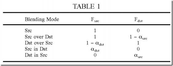
Table 1 gives the Fsrc and Fdst blending factors for the five Porter-Duff blending modes in OpenVG.
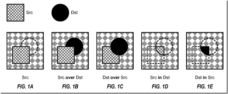
FIGS. 1A through 1E illustrate blending for the five Porter-Duff blending modes in OpenVG. In these examples, the source (Src) is represented by a square with cross hashing, and the destination (Dst) is represented by a circle with solid fill. FIG. 1A shows the “Src” blending mode. In this blendingmode, the source (square) replaces the background, and the destination (circle) is completely transparent. FIG. 1B shows the “Src over Dst” blendingmode. In this blending mode, the source replaces the destination and background, and the destination replaces the background. FIG. 1C shows the “Dst over Src” blending mode. In this blending mode, the destination replaces the source and background, and the source replaces the background. FIG. 1D shows the “Src in Dst” blending mode. In this blending mode, the portion of the source that is within the destination replaces the background. FIG. 1E shows the “Dst in Src” blending mode. In this blending mode, the portion of the destination that is within the source replaces the background.
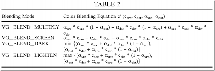
OpenVG supports four additional blending modes. Table 2 lists the four additional blending modes and gives the color blending equation for each mode. Each additional blending mode combines color values and provides a blended pre-multiplied color value denoted as c′(csrc,cdst,αsrc,αdst).
OpenVG further supports an additive blending mode that may be used when the source and destination do not overlap. The alpha and color blending equations for the additive blending mode are given as:

Other blending modes may also be supported for 2-D graphics. In general, a GPU may support any set of blending modes for any set of blending equations for 2-D graphics.
A GPU may also support various blending modes for 3-D graphics, e.g., the blending modes defined in Open Graphics Library (OpenGL), Direct3D, etc. OpenGL is described in a document entitled “The OpenGL® Graphics System: A Specification,” Version 2.0, dated Oct. 22, 2004, which is publicly available. OpenGL supports blending modes such as FUNC ADD (αsrc*csrc+αdst*cdst), FUNC SUBTRACT (αsrc*csrc−αdst*cdst), FUNC REVERSE SUBTRACT (αdst*cdst−αsrc*csrc), and MIN (min{csrc,cdst}), MAX (max{csrc,cdst}). Various blending factors may be used for the blending modes and are given in the OpenGL document. Direct3D similarly supports various blending modes and blending equations.
As described above, e.g., in equations (1) through (6) and Tables 1 and 2, there may be many equations for many blending modes. Direct implementation of the alpha and color blending equations for all blending modes in dedicated hardware may be complex and cost prohibitive.
In an aspect, the blending equations for supported blending modes (e.g., the blending modes in OpenVG and/or other blending modes) are efficiently implemented with a base set of operations. Each blending equation may be decomposed into a sequence of operations, with each operation taken from the base set. Different blending equations may be implemented with different sequences of operations. The base set of operations simplifies hardware implementation and provides flexibility to support various blending equations as well as other graphics functions and features.
FIG. 2 shows a design of a blending instruction 200 for an operation used for blending. In this design, blending instruction 200 includes a clamp enable field 212, a blending operation (Op) field 214, a result (Res) field 216, a destination (Dst) field 218, a source (Src) field 220, a destination blending factor (Dstf) field 222, and a source blending factor (Srcf) field 224. Blending Op field 214 indicates which operation in the base set to perform. Src field 220 indicates where a source value is stored. Dst field 218 indicates where a destination value is stored. Srcf field 224 indicates a source blending factor for the operation. Dstf field 222 indicates a destination blending factor for the operation. Res field 216 indicates where to store the result(s) of the operation. Clamp enable field 212 indicates whether to constrain the result(s) to a predetermined range of values, e.g., between 0 and 1. Other instruction formats with different fields may also be used.

Table 3 shows a design of the base set of operations and the Op code assigned to each operation. For each blending instruction, blending Op field 214 stores the Op code of the operation to be performed for that blending instruction. For simplicity, operations with Op codes 0 through 7 are referred to as operations 0 through 7, respectively.
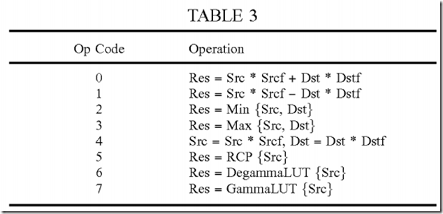
For operations 0 and 1, the source and destination values are scaled by the source and destination blending factors, respectively, and the scaled values are combined. Operation 0 performs a dot product of two operands with two blending factors. Operation 1 is a variant of the dot product. Operations 0 and 1 may be used for all of the blending modes described above. Operation 2 provides the smaller of the source and destination values whereas operation 3 provides the larger of the two values. Operations 2 and 3 may be used for the VG_BLEND_DARK, VG_BLEND_LIGHTEN, and additive blending modes. Operation 4 scales the source and destination values with the source and destination blending factors, respectively, and stores the two scaled values. Operation 4 may be used for conversion between pre-multiplied and non pre-multiplied color values.
Operation 5 performs a reciprocal (RCP) operation on a source value and provides a result value. The reciprocal operation is used to convert a divide operation into a multiply operation, which is typically much less complex. For example, a color value may be obtained from a pre-multiplied color value as c=c′/α. The division by alpha may be avoided by first obtaining the reciprocal of alpha (or 1/α) and then multiplying c′ with 1/α as follows: c=c′*(1/α). The reciprocal operation may also be used for equations (2) and (6), both of which include a division by a result alpha value.
Operations 6 and 7 are used for gamma expansion and gamma compression, respectively. Human eyes are more sensitive to low luminance/intensity than high luminance. A color value may be compressed via a process commonly referred to as gamma compression or gamma encoding. Gamma compression maps a color value such that finer resolution is achieved for low luminance and coarser resolution is achieved for high luminance. Gamma compression may be performed as ccomp=clinγ, where clin is a linear color value, ccomp is a compressed or non-linear color value, and γ is a gamma value that determines the amount of compression. In general, gamma compression may be performed based on any function or mapping. Gamma expansion is a complementary process that expands a compressed color value to obtain a linear color value. Gamma expansion is based on a function that is the inverse of the function used for gamma compression. Color components R, G and B are typically stored in memory as compressed color values.
In general, blending may be performed on linear or compressed color values. Improved results might be obtained by performing blending on linear color values. Hence, compressed color values may be retrieved from memory and expanded prior to blending. The blended color values may then be compressed prior to storing back to memory. Gamma compression may be achieved with a gamma look-up table (LUT) that stores the gamma compression function. Gamma expansion may be achieved with a degamma LUT that stores the complementary gamma expansion function. For operation 6, the degamma LUT receives a compressed color value and provides a linear color value. For operation 7, the gamma LUT receives a linear color value and provides a compressed color value.
Table 3 shows a specific design for a base set of operations. Other sets of operations may also be used to support blending.
Source color values may be received from a shader core and stored in a source register. Destination color values may be retrieved from a memory and stored in a destination register. The source and destination color values may be combined, and the blended color values may be stored in the destination register.
To flexibly support different operations, multiple source registers may be used to store source color and alpha values as well as intermediate values. Alternatively or additionally, multiple destination registers may be used to store destination color and alpha values as well as intermediate values. In one design, two source registers and two destination registers are used to store source, destination, and intermediate values. For each of operations 0 through 4 in Table 3, the Src and Dst may correspond to any two of the source and destination registers. For each of operations 5 through 7 in Table 3, the Src may correspond to any one of the source and destination registers. For each operation, the result(s) may be stored in the source and/or destination register, or back to memory.
Table 4 shows a design of the Src, Dst, and Res fields for blending instruction 200 in FIG. 2. For each blending instruction, Src field 220 may indicate any one of the four registers listed in the second column of Table 4, Dst field 218 may also indicate any one of the four registers, and Res field 216 may indicate any one of the six output options shown in the last column of Table 4. The source and destination registers (code 4 for Res) are both used for operation 4 in Table 3. Other designs with different registers and/or output options may also be used.
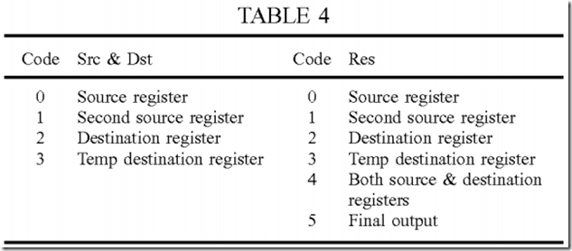
The Srcf and Dstf blending factors are used to scale the Src and Dst values, respectively, in operations 0, 1 and 4 in Table 3. The Srcf and Dstfblending factors may be defined to support all blending modes. Additional blending factors may also be defined to support other graphics functions and features (e.g., 3-D graphics).
Table 5 shows a design of the Srcf and Dstf blending factors for blending instruction 200 in FIG. 2. For each blending instruction, Srcf field 224 may indicate any one of the selections shown in Table 5, and Dstf field 222 may also indicate any one of these selections. A driver/compiler that generatesblending instructions may select the appropriate blending factor(s) for each blending instruction.
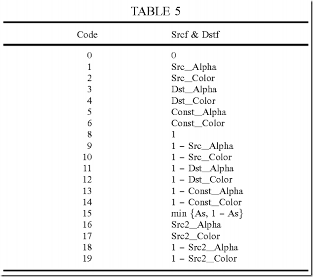
In Table 5, Src_Alpha and Src_Color are the alpha and color values, respectively, in the source register, Src2_Alpha and Src2_Color are the alpha and color values, respectively, in the second source register, Dst_Alpha and Dst_Color are the alpha and color values, respectively, in the destination register, and Const_Alpha and Const_Color are the alpha and color values, respectively, in a constant register.
The various blending modes may be efficiently implemented with the blending instruction, base set of operations, source and destination registers, and source and destination blending factors described above. For clarity, blending instructions for the blending modes in OpenVG are described in detail below. Each of the five Porter-Duff blending modes shown in equations (1) through (4) and Table 1 may be implemented with two instructions. The first instruction multiplies the source and destination color values with the source and destination alpha values, respectively. Table 6 gives the codes for the various fields of the first instruction.
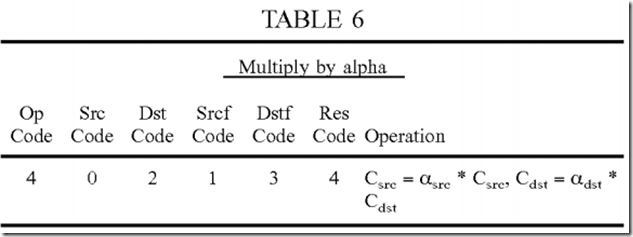
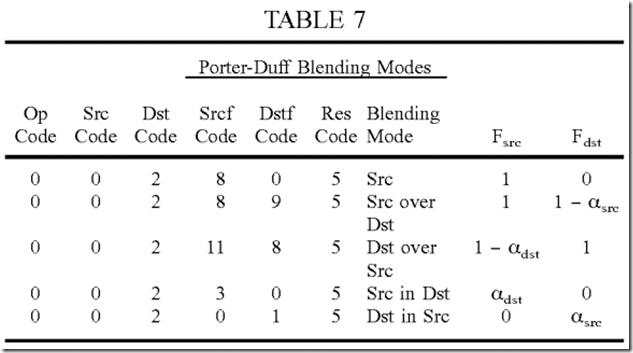
The second instruction multiplies the pre-multiplied source and destination color values with Fsrc and Fdst blending factors, respectively, and combines the two scaled values, as shown in equation (4). Table 7 gives the codes for the various fields of the second instruction for each of the five Porter-Duffblending modes in OpenVG.
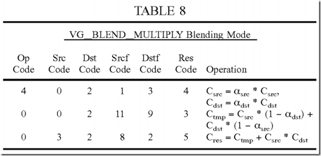
The VG_BLEND_MULTIPLY blending mode may be implemented with three instructions. The first instruction obtains the pre-multiplied source and destination color values. The second instruction computes αsrc*csrc*(1−αdst)+αdst*cdst*(1−αsrc) and stores the intermediate result in the temp destination register. The third instruction sums the intermediate result with αsrc*csrc*αdst*cdst. Table 8 gives the codes for the three instructions for the VG_BLEND_MULTIPLY blending mode.
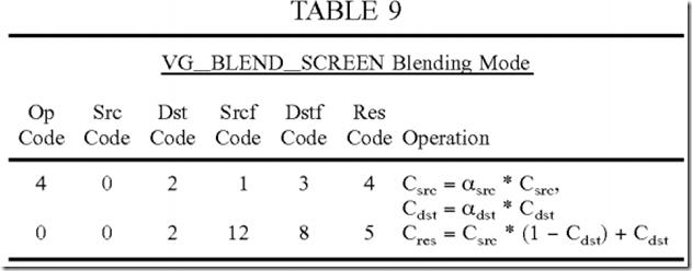
The VG_BLEND_SCREEN blending mode may be implemented with two instructions. The first instruction obtains the pre-multiplied source and destination color values. The second instruction computes αsrc*csrc+αdst*cdst−αsrc*csrc*αdst*cdst. Table 9 gives the codes for the two instructions for the VG_BLEND_SCREEN blending mode.
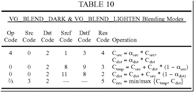
The VG_BLEND_DARK and VG_BLEND_LIGHTEN blending modes may each be implemented with four instructions. The first instruction obtains the pre-multiplied source and destination color values. The second instruction computes the left part of the min or max expression, which is (αsrc*csrc+αdst*cdst*(1−αsrc). The third instruction computes the right part of the min or max expression, which is (αdst*cdst+αsrc*csrc*(1−αdst). The fourth instruction performs the compare for the min or max expression. Table 10 gives the codes for the four instructions for the VG_BLEND_DARK and VG_BLEND_LIGHTEN blending modes.
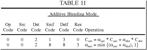
The additive blending mode in equations (5) and (6) may be implemented with four instructions. The first instruction computes the numerator of equation (6), which is αsrc*csrc+αdst*cdst. The second instruction computes the result alpha value in equation (5). The min operation is achieved by setting clamp enable field 212 in FIG. 2, which limits the result of (αsrc+αdst) to 1. The third instruction computes the reciprocal of the result alpha value. The fourth instruction multiplies the intermediate result from the first instruction with the reciprocal value from the third instruction. The instruction format shown in FIG. 2 may be used for both alpha and color operations. Multiple instructions (e.g., one for alpha and one for color) may be executed in parallel in the same clock cycle. The instructions for alpha and color may have different op codes and operands. Table 11 gives the codes for the four instructions for the additive blending mode. The second instruction is for alpha only and may be executed in parallel with the first instruction in the same clock cycle.
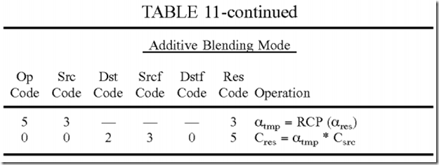
As illustrated above, all of the blending modes in OpenVG may be supported using a subset of the features shown in Tables 3 through 5. A GPU may be designed with the capability to support just the blending modes in OpenVG. A GPU may also be designed with additional features, e.g., as described above for Tables 3 through 5. These additional features may be used to support all blending modes of interest. For example, the FUNC REVERSE SUBTRACT blending mode for OpenGL may be emulated/implemented with operation 1 in Table 3 and selecting Src code of 2 for the destination register and Dst code of 0 for the source register. These additional features may also be used to support other graphics functions such as, e.g., stencil interpolation.
Stencil interpolation uses the following set of equations:
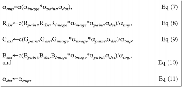
where αimage is a first source alpha value, αpaint is a second source alpha value, αsrc=αimage*αpaint for equation (7), and αsrc=αimage*αpaint*Rimage for equations (8) through (10).
Alpha blending equation (7) and color blending equations (8) through (10) may be dependent on blending mode. For example, if the “Src over Dst” Porter-Duff blending mode is selected, then the stencil interpolation may be expressed as:
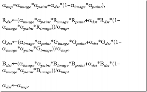
Various blending modes as well as other graphics functions may be supported as follows:
- 10 Call RCP to compute 1/alpha //Dst pre-format
- 20 Call MUL to divide alpha out of Dst
- 30 Call DeGammaLUT to convert compressed color to linear color
- 40 Op0: Src=alpha*Src, Dst=alpha*Dst //do blending
- 41 Op1: Instruction for mode-dependent blending equation
- . .
- . .
- . .
- 4n Opn: Instruction for mode-dependent blending equation
- 50 Call RCP to compute 1/alpha //Dst post-format
- 60 Call MUL to divide alpha out of Dst
- 70 Call GammaLUT to convert linear color to compressed color
- 80 Call MUL to multiply alpha with Dst and store Dst
Instructions 10 to 80 assume that color components are stored as pre-multiplied compressed color values. Instructions 10, 20 and 30 are for pre-formatting of the destination color value. Instructions 10 and 20 divide out alpha from the destination color value. Instruction 30 converts compressed color to linear color. Instructions 40 to 4n are for operations that are dependent on the selected blending mode. Instructions 50 to 80 are for post-formatting of the result color value. Instructions 50 and 60 divide out the result alpha to obtain a non pre-multiplied color value. Instruction 70 converts linear color to compressed color. Instruction 80 multiplies the compressed color value with alpha and stores the final result back to memory. Instructions 10, 20 and 80 may be omitted if the color values are stored in non pre-multiplied format. Instructions 30 and 70 may be omitted if color components are stored as linear color values instead of compressed color values.
An example design has been described above in Tables 3 through 5. In general, a blending processing unit may support any set of operations, any set of source and destination registers, and any set of blending factors. The supported set of operations may be used to implement any blending modes and possibly other graphics functions and features. For clarity, the design has been specifically described for the blending modes in OpenVG. The design may also be used for other blending modes.
The blending techniques described herein may be used for various types of processors such as GPUs, graphics processors, digital signal processors (DSPs), reduced instruction set computers (RISCs), advanced RISC machines (ARMs), controllers, microprocessors, etc. Exemplary use of the techniques for a GPU is described below.
FIG. 3 shows a block diagram of a design of a graphics system 300, which may be a stand-alone system or part of a larger system such as a computing system, a wireless communication device, etc. Graphics applications 310 may run concurrently and may be for video games, graphics, videoconference, etc. Graphics applications 310 generate high-level commands to perform graphics operations on graphics data. The high-level commands may be relatively complex. The graphics data may include geometry information (e.g., information for vertices of primitives in an image), information describing what the image looks like, etc. Application programming interfaces (APIs) 320 provide an interface between graphics applications310 and a GPU driver/compiler 330, which may be software and/or firmware executing on a processor.
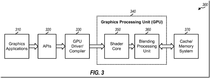
GPU driver/compiler 330 converts the high-level commands to low-level instructions, which may be machine dependent and tailored for the underlying processing units. GPU driver/compiler 330 also indicates where graphics data is located, e.g., which buffers store the data. GPU driver/compiler 330 may split the processing of each application into a series of threads, e.g., automatically and transparent to the application. A thread (or thread of execution) indicates a specific task that may be performed with a set of one or more instructions. For example, a thread may perform blending for some number of pixels. Threads allow an application to have multiple tasks performed simultaneously by different units and further allow different applications to share resources.
A GPU 340 includes a shader core 350 and a blending processing unit 360. The terms “core”, “engine”, “machine”, “processor” and “processing unit” are often used interchangeably. Shader core 350 may perform graphics operations such as shading, texture mapping, etc. Blending processing unit 360 performs blending and may support any number of blending modes. GPU 340 may also include other processing units (e.g., a texture engine) that are not shown in FIG. 3 for simplicity.
A cache/memory system 370 may store instructions and data for GPU 340. System 370 may include one or more caches, which are fast memories that can be accessed more quickly.
FIG. 4 shows a block diagram of a design of blending processing unit 360 in FIG. 3. A source register 412 receives and stores source color and alpha values (e.g., from shader core 350 in FIG. 3) and/or intermediate results from a blending execution unit 410. A second source register 414 stores additional color and alpha values and/or intermediate results. Blending processing unit 360 may receive one or two sets of source RGB color values for each pixel from shader core 350 and may store each set of source color values in one of source registers 412 and 414. Blending processing unit 360 may perform blending on up to two colors for each pixel.
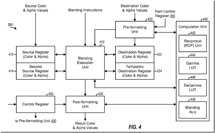
A pre-formatting unit 420 receives destination color and alpha values (e.g., from memory 370 in FIG. 3) and performs pre-formatting. Unit 420 may divide out alpha for pre-multiplied color values, perform conversion from compressed color to linear color, etc. A destination register 422 stores pre-formatted destination color and alpha values from pre-formatting unit 420 and/or intermediate results from blending execution unit 410. A temporary destination register 424 stores intermediate results.
Blending execution unit 410 receives blending instructions (e.g., from GPU driver/compiler 330 via shader core 350 in FIG. 3) and decodes the received instructions. Unit 410 also reads source and destination values and blending factors according to the decoded instructions and sends these values and factors to a computation unit 440 for processing. Unit 410 receives results from unit 440 and stores these results in the appropriate registers. A post-formatting unit 430 performs post-formatting on the results and may divide out alpha for pre-multiplied color values, perform conversion from linear color to compressed color, multiply by alpha if the result color values are to be stored in pre-multiplied format, etc.
Unit 440 includes a reciprocal (RCP) unit 442, a gamma LUT 444, a degamma LUT 446, and a blending ALU 448. Blending ALU 448 may perform operations 0 through 4 in Table 3. Blender ALU 448 may operate on operands received from unit 410, 420 and 430 and provide the results back to these units. Unit 442 receives input operands and provides the reciprocal of the operands. Gamma LUT 444 receives linear color values and provides compressed color values. Degamma LUT 446 receives compressed color values and provides linear color values. Blending execution unit 410, pre-formatting unit 420, and post-formatting unit 430 may call reciprocal unit 442, gamma LUT 444, degamma LUT 446, and blending ALU 448 as needed, e.g., to perform the operations indicated by the blending instructions, to multiply by alpha or 1/alpha, etc. Blending execution unit 410 may also call gamma LUT 444 and degamma LUT 446 for certain blending modes or special functions. For example, the source values from shader core 350 may be in linear format and a blending mode may operate in compressed format. In this case, blending execution unit 410 may call gamma LUT 444 to convert the source values to compressed format, perform the blending operation, and then call degamma LUT 446 to convert the results back to linear format.
A control register 450 stores control bits that indicate the format of the data being processed. For example, the control bits may indicate whether color values are stored in (a) pre-multiplied or non pre-multiplied format and (b) compressed or linear format. Unit 420 may perform pre-formatting on inbound destination color values in accordance with the control bits. Similarly, unit 430 may perform post-formatting on outbound color values in accordance with the control bits. Control register 450 may be set by GPU driver/compiler 330 or some other unit.
Pre-formatting unit 420, blending execution unit 410, and post-formatting unit 430 may operate in a pipelined manner on a given thread. Unit 410, 420and 430 may also operate on multiple threads concurrently. For example, in a given clock cycle, unit 420 may perform pre-formatting for one thread, unit410 may perform processing for another thread, and unit 430 may perform post-formatting for yet another thread. Units 410, 420 and 430 may invoke units 442, 444, 446 and 448 as needed.
The blending processing unit (or blending unit) described herein may be low cost and may support all of the blending modes in OpenVG. The blendingunit is flexible and may be able to support other blending modes and blending features. The blending unit may also be used for load balancing with other processing units. For example, some operations may be moved to another processing unit (e.g., shader core 350) to relieve loading of the blending unit, or the blending unit may perform operations for other processing units, to balance the workload between these units. The blending unit may be designed to meet 3-D graphics standards (e.g., OpenGL ES2.0, Direct3D, etc.), OpenVG standard, and/or other standards. The flexible and programmable nature of the blending unit allows it to meet future extensions of these standards by simply re-writing the blending instructions without having to re-design theblending unit.
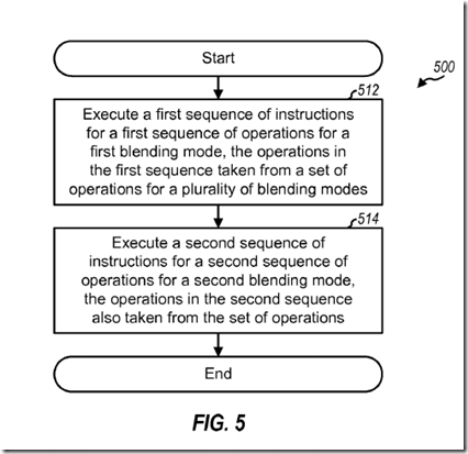
FIG. 5 shows a process 500 for performing blending. A first sequence of instructions is executed for a first sequence of operations for a first blendingmode (block 512). A second sequence of instructions is executed for a second sequence of operations for a second blending mode (block 514). The operations in the first and second sequences are from a set of operations for a plurality of blending modes comprising the first and second blendingmodes. The first and second sequences of instructions may be generated by GPU driver/compiler 330 or some other unit and may be stored in shader core 350, blending processing unit 360, or some other unit. A sequence may include an instruction for a dot product of two operands with two blendingfactors, an instruction for a reciprocal of an operand, an instruction to convert linear color to compressed color, an instruction to convert compressed color to linear color, etc.
The blending techniques described herein may be used for wireless communication devices, handheld devices, gaming devices, computing devices, networking devices, personal electronics devices, etc. An exemplary use of the techniques for a wireless communication device is described below.
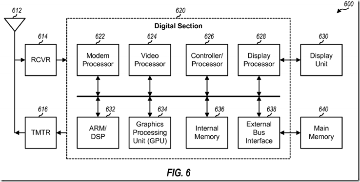
FIG. 6 shows a block diagram of a design of a wireless communication device 600 in a wireless communication system. Wireless device 600 may be a cellular phone, a terminal, a handset, a personal digital assistant (PDA), or some other device. The wireless communication system may be a Code Division Multiple Access (CDMA) system, a Global System for Mobile Communications (GSM) system, or some other system.
Wireless device 600 is capable of providing bi-directional communication via a receive path and a transmit path. On the receive path, signals transmitted by base stations are received by an antenna 612 and provided to a receiver (RCVR) 614. Receiver 614 conditions and digitizes the received signal and provides samples to a digital section 620 for further processing. On the transmit path, a transmitter (TMTR) 616 receives data to be transmitted from digital section 620, processes and conditions the data, and generates a modulated signal, which is transmitted via antenna 612 to the base stations.
The blending processing unit and GPU described herein may be stand-alone units or may be part of a device. The device may be (i) a stand-alone IC such as a graphics IC, (ii) a set of one or more ICs that may include memory ICs for storing data and/or instructions, (iii) an ASIC, such as a mobile station modem (MSM), with integrated graphics processing functions, (iv) a module that may be embedded within other devices, (v) a cellular phone, wireless device, handset, or mobile unit, (vi) etc.
For a firmware and/or software implementation, the blending techniques may be implemented with modules (e.g., procedures, functions, and so on) that perform the functions described herein. The firmware and/or software codes may be stored in a memory (e.g., memory 636 or 640 in FIG. 6) and executed by a processor (e.g., processor 626). The memory may be implemented within the processor or external to the processor.
SRC=http://www.freepatentsonline.com/y2008/0094410.html
PatentTips - GPU Support for Blending的更多相关文章
- Ubuntu 16.04 + CUDA 8.0 + cuDNN v5.1 + TensorFlow(GPU support)安装配置详解
随着图像识别和深度学习领域的迅猛发展,GPU时代即将来临.由于GPU处理深度学习算法的高效性,使得配置一台搭载有GPU的服务器变得尤为必要. 本文主要介绍在Ubuntu 16.04环境下如何配置Ten ...
- 谈谈TensorFlow with CPU support or TensorFlow with GPU support(图文详解)
不多说,直接上干货! You must choose one of the following types of TensorFlow to install: TensorFlow with CPU ...
- detectron2安装出现Kernel not compiled with GPU support 报错信息
在安装使用detectron2的时候碰到Kernel not compiled with GPU support 问题,前后拖了好久都没解决,现总结一下以备以后查阅. 不想看心路历程的可以直接跳到最后 ...
- PatentTips – GPU Saving and Restoring Thread Group Operating State
BACKGROUND OF THE INVENTION The present invention relates generally to single-instruction, multiple- ...
- Caffe学习笔记2--Ubuntu 14.04 64bit 安装Caffe(GPU版本)
0.检查配置 1. VMWare上运行的Ubuntu,并不能支持真实的GPU(除了特定版本的VMWare和特定的GPU,要求条件严格,所以我在VMWare上搭建好了Caffe环境后,又重新在Windo ...
- caffe 无GPU 环境搭建
root@k-Lenovo:/home/k# sudo apt-get install libprotobuf-dev libleveldb-dev libsnappy-dev libopencv-d ...
- linux 安装tensorflow(gpu版本)
一.安装cuda 具体安装过程见我的另一篇博客,ubuntu16.04下安装配置深度学习环境 二.安装tensorflow 1.具体安装过程官网其实写的比较详细,总结一下的话可以分为两种:安装rele ...
- 在浏览器中运行Keras模型,并支持GPU
Keras.js 推荐一下网页上的 demo https://transcranial.github.io/keras-js/#/ 加载的比较慢,但是识别的非常快. Run Keras models ...
- caffe安装教程(Ubuntu14+GPU+pycaffe+anaconda2)
caffe安装教程 本文所使用的底层环境配置:cuda8.cudnn6.OpenCV2.4.5.anaconda2(Python2.7).如使用其他版本的环境,如cuda,可安装自己的版本,但须在相应 ...
随机推荐
- Android(java)学习笔记147:自定义SmartImageView(继承自ImageView,扩展功能为自动获取网络路径图片)
1. 有时候Android系统配置的UI控件,不能满足我们的需求,Android开发做到了一定程度,多少都会用到自定义控件,一方面是更加灵活,另一方面在大数据量的情况下自定义控件的效率比写布局文件更高 ...
- winhex与磁盘格式与 数据恢复
第一阶段: 熟悉WinHex的使用. n 熟悉磁盘工具的使用. n 利用WinHex查看物理磁盘和逻辑磁盘. n 了解WinHex中相关工具的用法. 以管理员身份运行winhex(以便之后修改) 上方 ...
- 【Selenium-WebDriver问题点】driver和浏览器版本之间的兼容性问题
今天把手头有的一些关于selenium测试的资源整理了一下,分享出来. 1. 所有版本chrome下载 是不是很难找到老版本的chrome?博主收集了几个下载chrome老版本的网站,其中哪个下载的是 ...
- Java加腾讯云实现短信验证码功能
一.概要 现如今在日常工作和生活中短信验证码对于我们来说是非常熟悉的,比较常见的注册账号或者交易支付时候,手机会收到一个短信验证码,我们可以通过验证码来有效验证身份,避免一些信息被盗. 验证身份 目前 ...
- 使用crontab定时执行python文件问题追根溯源
使用crontab执行定时任务不是第一次用,昨天下午设置几个任务,yy里面已存在的任务,修改指定python环境和执行文件路径后,死活到点不执行. 任务设置如下: 15 16 * * * /root/ ...
- 多线程下载命令--axel
axel是轻量级多线程下载工具,对比传统下载工具curl和wget,下载速度上提升不少 centos安装如下 yum install -y axel 命令行用法 axel [option] url1 ...
- 函数的参数是函数,函数中Ajax返回的回调函数中的函数运行
调用函数 checkAjax('addrinfo',formdata,vzxcv); 函数checkAjax function checkAjax(url,formdata,call_back){ / ...
- Bootstrap 网格系统(Grid System)实例5
Bootstrap 网格系统(Grid System)实例5:手机,平板电脑,笔记本或台式电脑 <!DOCTYPE html><html><head><met ...
- CS193p Lecture 10 - Multithreating, UIScrollView
Multithreating(多线程) 网络请求例子: NSURLRequest *request = [NSURLRequest requestWithURL:[NSURL URLWithStrin ...
- hihoCoder-1098-kruskal
如果起始点和终止点的父节点相同,就说明它们就已经在同一个连通分量里面,说明,起始点和终止点在此之前就已经被连入同一个分量之中,如果此时还将起始点和终止点连入此分量,就会形成回路,想象一个三角形,你大概 ...
