包格式及IP地址,网络层协议
包格式及IP地址,网络层协议
1 案例1:配置静态路由
1.1 问题
配置路由接口IP地址并通过静态路由的配置实现全网的互通。
1.2 方案
按如下网络拓扑配置接口IP地址并通过静态路由的配置实现全网的互通如图-1所示:
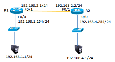
图-1
1.3 步骤
实现此案例需要按照如下步骤进行。
步骤一:配置静态路由
1)R1上配置接口IP
- R1(config)#interface fastEthernet 0/0
- R1(config-if)#ip address 192.168.1.254 255.255.255.0
- R1(config-if)#no shutdown
- R1(config-if)#exit
- R1(config)#interface fastEthernet 0/1
- R1(config-if)#ip address 192.168.2.1 255.255.255.0
- R1(config-if)#no shutdown
2)R2上配置接口IP
- R2(config)#interface fastEthernet 0/1
- R2(config-if)#ip address 192.168.2.2 255.255.255.0
- R2(config-if)#no shutdown
- R2config-if)#exit
- R2(config)#interface fastEthernet 0/0
- R2(config-if)#ip address 192.168.4.254 255.255.255.0
- R2(config-if)#no shutdown
3)R1上添加静态路由
- R1(config)#ip route 192.168.4.0 255.255.255.0 192.168.2.2
4)R1上查看路由表
- R1#show ip route
- Codes: C - connected, S - static, I - IGRP, R - RIP, M - mobile, B - BGP
- D - EIGRP, EX - EIGRP external, O - OSPF, IA - OSPF inter area
- N1 - OSPF NSSA external type 1, N2 - OSPF NSSA external type 2
- E1 - OSPF external type 1, E2 - OSPF external type 2, E - EGP
- i - IS-IS, L1 - IS-IS level-1, L2 - IS-IS level-2, ia - IS-IS inter area
- * - candidate default, U - per-user static route, o - ODR
- P - periodic downloaded static route
- Gateway of last resort is not set
- C 192.168.1.0/24 is directly connected, FastEthernet0/0
- C 192.168.2.0/24 is directly connected, FastEthernet0/1
- S 192.168.4.0/24 [1/0] via 192.168.2.2 //S表示静态路由
5)R2上添加静态路由
- R2(config)#ip route 192.168.1.0 255.255.255.0 192.168.2.1
6)R2上查看路由条目
- R2#show ip route
- Codes: C - connected, S - static, I - IGRP, R - RIP, M - mobile, B - BGP
- D - EIGRP, EX - EIGRP external, O - OSPF, IA - OSPF inter area
- N1 - OSPF NSSA external type 1, N2 - OSPF NSSA external type 2
- E1 - OSPF external type 1, E2 - OSPF external type 2, E - EGP
- i - IS-IS, L1 - IS-IS level-1, L2 - IS-IS level-2, ia - IS-IS inter area
- * - candidate default, U - per-user static route, o - ODR
- P - periodic downloaded static route
- Gateway of last resort is not set
- S 192.168.1.0/24 [1/0] via 192.168.2.1 //S表示静态路由
- C 192.168.2.0/24 is directly connected, FastEthernet0/1
- C 192.168.3.0/24 is directly connected, FastEthernet0/0
7)配置PC1的IP地址为192.168.1.1,网关为192.168.1.254
8)配置PC2的IP地址为192.168.4.1,网关为192.168.4.254
9)测试网络连通性,PC1 ping 192.168.4.1
- PC>ping 192.168.4.1
- Pinging 192.168.4.1 with 32 bytes of data:
- Reply from 192.168.4.1: bytes=32 time=1ms TTL=126
- Reply from 192.168.4.1: bytes=32 time=11ms TTL=126
- Reply from 192.168.4.1: bytes=32 time=10ms TTL=126
- Reply from 192.168.4.1: bytes=32 time=11ms TTL=126
- Ping statistics for 192.168.4.1:
- Packets: Sent = 4, Received = 4, Lost = 0 (0% loss),
- Approximate round trip times in milli-seconds:
- Minimum = 1ms, Maximum = 11ms, Average = 8ms
2 案例2:配置浮动路由
2.1 问题
配置浮动静态路由
2.2 方案
按如下网络拓扑配置接口IP地址配置浮动路由实现链路的冗余,如图-2所示
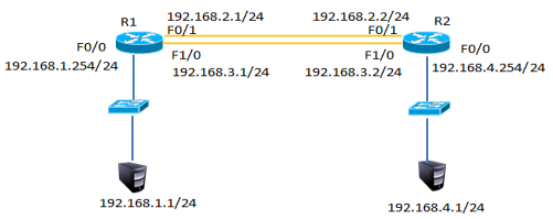
图-2
2.3 步骤
实现此案例需要按照如下步骤进行。
步骤一:配置静态路由并添加模块
1)R1上配置接口IP
在以上静态路由实验的基础上,先分别进入R1与R2的特权模式输入write命令保存配置信息,然后分别进入R1与R2的物理配置界面,点击开关按钮关闭路由器,添加NM-1FE-TX模块并再次点击开关按钮,如下图-3所示。
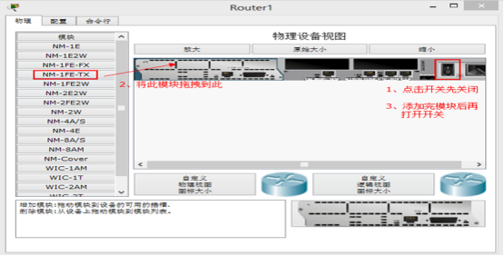
图-3
2)添加模块后将R1的F1/0接口连接到R2的F1/0接口修改拓扑如下图-4所示:
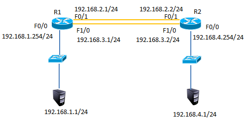
图-4
3)配置R1的F1/0接口IP
- R1(config)#interface fastEthernet 1/0
- R1(config-if)#ip address 192.168.3.1 255.255.255.0
- R1(config-if)#no shutdown
4)配置R2的F1/0接口IP
- R2(config)#interface fastEthernet 1/0
- R2(config-if)#ip address 192.168.3.2 255.255.255.0
- R2(config-if)#no shutdown
5)R1上添加静态浮动路由
- R1(config)#ip route 192.168.4.0 255.255.255.0 192.168.3.2 50 //管理距离50
6)R2上添加静态浮动路由
- R2(config)#ip route 192.168.1.0 255.255.255.0 192.168.3.1 50 //管理距离50
7)R1上查看路由表
- R1#show ip route
- Codes: C - connected, S - static, I - IGRP, R - RIP, M - mobile, B - BGP
- D - EIGRP, EX - EIGRP external, O - OSPF, IA - OSPF inter area
- N1 - OSPF NSSA external type 1, N2 - OSPF NSSA external type 2
- E1 - OSPF external type 1, E2 - OSPF external type 2, E - EGP
- i - IS-IS, L1 - IS-IS level-1, L2 - IS-IS level-2, ia - IS-IS inter area
- * - candidate default, U - per-user static route, o - ODR
- P - periodic downloaded static route
- Gateway of last resort is not set
- C 192.168.1.0/24 is directly connected, FastEthernet0/0
- C 192.168.2.0/24 is directly connected, FastEthernet0/1
- C 192.168.3.0/24 is directly connected, FastEthernet1/0
- S 192.168.4.0/24 [1/0] via 192.168.2.2 //只有下一跳为192.168.2.2的静态路由
8)禁用F/01接口
- R1(config)#interface fastEthernet 0/1
- R1(config-if)#shutdown
9)R1上查看路由表
- C 192.168.1.0/24 is directly connected, FastEthernet0/0
- S 192.168.4.0/24 [50/0] via 192.168.3.2//下一跳接口为192.168.4.2的路由生效
- C 192.168.4.0/24 is directly connected, FastEthernet1/0
10)测试网络连通性,PC1 ping 192.168.4.1
- PC>ping 192.168.4.1
- Pinging 192.168.4.1 with 32 bytes of data:
- Reply from 192.168.4.1: bytes=32 time=0ms TTL=126
- Reply from 192.168.4.1: bytes=32 time=10ms TTL=126
- Reply from 192.168.4.1: bytes=32 time=11ms TTL=126
- Reply from 192.168.4.1: bytes=32 time=1ms TTL=126
- Ping statistics for 192.168.4.1:
- Packets: Sent = 4, Received = 4, Lost = 0 (0% loss),
- Approximate round trip times in milli-seconds:
- Minimum = 0ms, Maximum = 11ms, Average = 5ms
3 案例3:配置多路由的静态路由
3.1 问题
配置多路由的静态路由
3.2 方案
网络环境及IP地址规划,如图-5所示
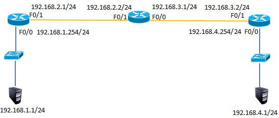
图-5
3.3 步骤
实现此案例需要按照如下步骤进行。
步骤一:配置路由IP和静态路由
1) R1上配置接口IP
- Router(config)#interface fastEthernet 0/0
- R1(config-if)#ip address 192.168.1.254 255.255.255.0
- R1(config-if)#no shutdown
- R1(config-if)#exit
- R1(config)#interface fastEthernet 0/1
- R1(config-if)#ip address 192.168.2.1 255.255.255.0
- R1(config-if)#no shutdown
2)R2上配置接口IP
- R2(config)#interface f0/1
- R2(config-if)#ip address 192.168.2.2 255.255.255.0
- R2(config-if)#no shutdown
- R2(config-if)#exit
- R2(config)#interface fastEthernet 0/0
- R2(config-if)#ip address 192.168.3.1 255.255.255.0
- R2(config-if)#no shutdown
3)R3上配置接口IP
- R3(config)#interface fastEthernet 0/1
- R3(config-if)#ip address 192.168.3.2 255.255.255.0
- R3(config-if)#no shutdown
- R3(config-if)#exit
- R3(config)#interface fastEthernet 0/0
- R3(config-if)#ip address 192.168.4.254 255.255.255.0
- R3(config-if)#no shutdown
4)R1、R2、R3上分别添加静态路由
- R1(config)#ip route 192.168.3.0 255.255.255.0 192.168.2.2
- R1(config)#ip route 192.168.4.0 255.255.255.0 192.168.2.2
- R2(config)#ip route 192.168.1.0 255.255.255.0 192.168.2.1
- R2(config)#ip route 192.168.4.0 255.255.255.0 192.168.3.2
- R3(config)#ip route 192.168.1.0 255.255.255.0 192.168.3.1
- R3(config)#ip route 192.168.2.0 255.255.255.0 192.168.3.1
5)R1上查看路由表
- R1#show ip route
- Codes: C - connected, S - static, I - IGRP, R - RIP, M - mobile, B - BGP
- D - EIGRP, EX - EIGRP external, O - OSPF, IA - OSPF inter area
- N1 - OSPF NSSA external type 1, N2 - OSPF NSSA external type 2
- E1 - OSPF external type 1, E2 - OSPF external type 2, E - EGP
- i - IS-IS, L1 - IS-IS level-1, L2 - IS-IS level-2, ia - IS-IS inter area
- * - candidate default, U - per-user static route, o - ODR
- P - periodic downloaded static route
- Gateway of last resort is not set
- C 192.168.1.0/24 is directly connected, FastEthernet0/0
- C 192.168.2.0/24 is directly connected, FastEthernet0/1
- S 192.168.3.0/24 [1/0] via 192.168.2.2 //静态路由
- S 192.168.4.0/24 [1/0] via 192.168.2.2 //静态路由
6)R2上查看路由表
- R2#show ip route
- Codes: C - connected, S - static, I - IGRP, R - RIP, M - mobile, B - BGP
- D - EIGRP, EX - EIGRP external, O - OSPF, IA - OSPF inter area
- N1 - OSPF NSSA external type 1, N2 - OSPF NSSA external type 2
- E1 - OSPF external type 1, E2 - OSPF external type 2, E - EGP
- i - IS-IS, L1 - IS-IS level-1, L2 - IS-IS level-2, ia - IS-IS inter area
- * - candidate default, U - per-user static route, o - ODR
- P - periodic downloaded static route
- Gateway of last resort is not set
- S 192.168.1.0/24 [1/0] via 192.168.2.1 //静态路由
- C 192.168.2.0/24 is directly connected, FastEthernet0/1
- C 192.168.3.0/24 is directly connected, FastEthernet0/0
- S 192.168.4.0/24 [1/0] via 192.168.3.2 //静态路由
7)R3上查看路由表
- R3#show ip route
- Codes: C - connected, S - static, I - IGRP, R - RIP, M - mobile, B - BGP
- D - EIGRP, EX - EIGRP external, O - OSPF, IA - OSPF inter area
- N1 - OSPF NSSA external type 1, N2 - OSPF NSSA external type 2
- E1 - OSPF external type 1, E2 - OSPF external type 2, E - EGP
- i - IS-IS, L1 - IS-IS level-1, L2 - IS-IS level-2, ia - IS-IS inter area
- * - candidate default, U - per-user static route, o - ODR
- P - periodic downloaded static route
- Gateway of last resort is not set
- S 192.168.1.0/24 [1/0] via 192.168.3.1 //静态路由
- S 192.168.2.0/24 [1/0] via 192.168.3.1 //静态路由
- C 192.168.3.0/24 is directly connected, FastEthernet0/1
- C 192.168.4.0/24 is directly connected, FastEthernet0/0
8)按图-4配置PC的IP地址
9)测试网络连通性,PC1 ping 192.168.2.2、192.168.3.1、192.168.3.2、192.168.4.1
- PC>ping 192.168.2.2 //ping 192.168.2.2
- Pinging 192.168.2.2 with 32 bytes of data:
- Reply from 192.168.2.2: bytes=32 time=0ms TTL=254
- Reply from 192.168.2.2: bytes=32 time=0ms TTL=254
- Reply from 192.168.2.2: bytes=32 time=0ms TTL=254
- Reply from 192.168.2.2: bytes=32 time=0ms TTL=254
- Ping statistics for 192.168.2.2:
- Packets: Sent = 4, Received = 4, Lost = 0 (0% loss),
- Approximate round trip times in milli-seconds:
- Minimum = 0ms, Maximum = 0ms, Average = 0ms
- PC>ping 192.168.3.1 //ping 192.168.3.1
- Pinging 192.168.3.1 with 32 bytes of data:
- Reply from 192.168.3.1: bytes=32 time=0ms TTL=254
- Reply from 192.168.3.1: bytes=32 time=3ms TTL=254
- Reply from 192.168.3.1: bytes=32 time=0ms TTL=254
- Reply from 192.168.3.1: bytes=32 time=0ms TTL=254
- Ping statistics for 192.168.3.1:
- Packets: Sent = 4, Received = 4, Lost = 0 (0% loss),
- Approximate round trip times in milli-seconds:
- Minimum = 0ms, Maximum = 3ms, Average = 0ms
- PC>ping 192.168.3.2 //ping 192.168.3.2
- Pinging 192.168.3.2 with 32 bytes of data:
- Reply from 192.168.3.2: bytes=32 time=0ms TTL=253
- Reply from 192.168.3.2: bytes=32 time=12ms TTL=253
- Reply from 192.168.3.2: bytes=32 time=0ms TTL=253
- Reply from 192.168.3.2: bytes=32 time=12ms TTL=253
- Ping statistics for 192.168.3.2:
- Packets: Sent = 4, Received = 4, Lost = 0 (0% loss),
- Approximate round trip times in milli-seconds:
- Minimum = 0ms, Maximum = 12ms, Average = 6ms
- PC>ping 192.168.4.1 //ping 192.168.4.1
- Pinging 192.168.4.1 with 32 bytes of data:
- Reply from 192.168.4.1: bytes=32 time=0ms TTL=125
- Reply from 192.168.4.1: bytes=32 time=10ms TTL=125
- Reply from 192.168.4.1: bytes=32 time=0ms TTL=125
- Reply from 192.168.4.1: bytes=32 time=22ms TTL=125
- Ping statistics for 192.168.4.1:
- Packets: Sent = 4, Received = 4, Lost = 0 (0% loss),
- Approximate round trip times in milli-seconds:
- Minimum = 0ms, Maximum = 22ms, Average = 8ms
4 案例4:配置默认路由
4.1 问题
配置默认路由
4.2 方案
网络环境及IP地址规划,如图-6所示

图-6
4.3 步骤
1)在案例3基础上删除R1与R3的静态路由
- R1(config)#no ip route 192.168.3.0 255.255.255.0 192.168.2.2
- R1(config)#no ip route 192.168.4.0 255.255.255.0 192.168.2.2
- R3(config)#no ip route 192.168.1.0 255.255.255.0 192.168.3.1
- R3(config)#no ip route 192.168.2.0 255.255.255.0 192.168.3.1
2)R1、R3添加默认路由
- R1(config)#ip route 0.0.0.0 0.0.0.0 192.168.2.2
- R3(config)#ip route 0.0.0.0 0.0.0.0 192.168.3.1
- 12)R1上查看路由表
- R1#show ip route
- Codes: C - connected, S - static, I - IGRP, R - RIP, M - mobile, B - BGP
- D - EIGRP, EX - EIGRP external, O - OSPF, IA - OSPF inter area
- N1 - OSPF NSSA external type 1, N2 - OSPF NSSA external type 2
- E1 - OSPF external type 1, E2 - OSPF external type 2, E - EGP
- i - IS-IS, L1 - IS-IS level-1, L2 - IS-IS level-2, ia - IS-IS inter area
- * - candidate default, U - per-user static route, o - ODR
- P - periodic downloaded static route
- Gateway of last resort is 192.168.2.2 to network 0.0.0.0
- C 192.168.1.0/24 is directly connected, FastEthernet0/0
- C 192.168.2.0/24 is directly connected, FastEthernet0/1
- S* 0.0.0.0/0 [1/0] via 192.168.2.2 //默认路由
3)R1、R3上查看路由表
- R1#show ip route
- Codes: C - connected, S - static, I - IGRP, R - RIP, M - mobile, B - BGP
- D - EIGRP, EX - EIGRP external, O - OSPF, IA - OSPF inter area
- N1 - OSPF NSSA external type 1, N2 - OSPF NSSA external type 2
- E1 - OSPF external type 1, E2 - OSPF external type 2, E - EGP
- i - IS-IS, L1 - IS-IS level-1, L2 - IS-IS level-2, ia - IS-IS inter area
- * - candidate default, U - per-user static route, o - ODR
- P - periodic downloaded static route
- Gateway of last resort is 192.168.3.1 to network 0.0.0.0
- C 192.168.1.0/24 is directly connected, FastEthernet0/0
- C 192.168.2.0/24 is directly connected, FastEthernet0/1
- S* 0.0.0.0/0 [1/0] via 192.168.2.2 //默认路由
- R3#show ip route
- Codes: C - connected, S - static, I - IGRP, R - RIP, M - mobile, B - BGP
- D - EIGRP, EX - EIGRP external, O - OSPF, IA - OSPF inter area
- N1 - OSPF NSSA external type 1, N2 - OSPF NSSA external type 2
- E1 - OSPF external type 1, E2 - OSPF external type 2, E - EGP
- i - IS-IS, L1 - IS-IS level-1, L2 - IS-IS level-2, ia - IS-IS inter area
- * - candidate default, U - per-user static route, o - ODR
- P - periodic downloaded static route
- Gateway of last resort is 192.168.3.1 to network 0.0.0.0
- C 192.168.3.0/24 is directly connected, FastEthernet0/1
- C 192.168.4.0/24 is directly connected, FastEthernet0/0
- S* 0.0.0.0/0 [1/0] via 192.168.3.1 //默认路由
4)测试网络连通性,PC1 ping 192.168.4.1
- PC>ping 192.168.4.1
- Pinging 192.168.4.1 with 32 bytes of data:
- Reply from 192.168.4.1: bytes=32 time=1ms TTL=125
- Reply from 192.168.4.1: bytes=32 time=0ms TTL=125
- Reply from 192.168.4.1: bytes=32 time=14ms TTL=125
- Reply from 192.168.4.1: bytes=32 time=14ms TTL=125
- Ping statistics for 192.168.4.1:
- Packets: Sent = 4, Received = 4, Lost = 0 (0% loss),
- Approximate round trip times in milli-seconds:
- Minimum = 0ms, Maximum = 14ms, Average = 7ms = 0ms,平均 = 0ms
包格式及IP地址,网络层协议的更多相关文章
- 详解BLE 空中包格式—兼BLE Link layer协议解析
BLE有几种空中包格式?常见的PDU命令有哪些?PDU和MTU的区别是什么?DLE又是什么?BLE怎么实现重传的?BLE ACK机制原理是什么?希望这篇文章能帮你回答以上问题. 虽然BLE空中包(pa ...
- DNS反射放大攻击分析——DNS反射放大攻击主要是利用DNS回复包比请求包大的特点,放大流量,伪造请求包的源IP地址为受害者IP,将应答包的流量引入受害的服务器
DNS反射放大攻击分析 摘自:http://www.shaojike.com/2016/08/19/DNS%E6%94%BE%E5%A4%A7%E6%94%BB%E5%87%BB%E7%AE%80%E ...
- IP数据报格式和IP地址路由
一.IP数据报格式 IP数据报格式如下: 注:需要注意的是网络数据包以大端字节序传输,当然头部也得是大端字节序,也就是说: The most significant bit is numbered 0 ...
- 自定义Nginx日志格式获取IP地址的省市份信息
注:图片如果损坏,点击文章链接:https://www.toutiao.com/i6806672112477012493/ 在linux中nginx日志产生的格式是下面的配置: $remote_add ...
- [转帖]IP /TCP协议及握手过程和数据包格式中级详解
IP /TCP协议及握手过程和数据包格式中级详解 https://www.toutiao.com/a6665292902458982926/ 写的挺好的 其实 一直没闹明白 网络好 广播地址 还有 网 ...
- LinuxC下获取UDP包中的路由目的IP地址和头标识目的地址
在接受到UDP包后,有时候我们需要根据所接收到得UDP包,获取它的路由目的IP地址和头标识目的地址. (一)主要的步骤: 在setsockopt中设置IP_PKTINFO,然后通过recvmsg来获取 ...
- 计算机网络中七层,五层,四层协议;IP 地址子网划分
七层协议: 7 应用层(http) 6 表示层(上层用户可以相互识别的数据:jpg) 5 会话层(不同主机不同线程间的通信) 4 运输层(tcp/ip:传输层提供端到端的透明数据服务)/差错控制和流量 ...
- 网络协议 2 - IP 地址和 MAC 地址
了解完网络协议,我们会发现,网络通信的五层模型里,有两个很重要的概念:IP 地址和 MAC 地址. 那么 IP 地址是怎么来的,又是怎么没的?MAC 地址与 IP 地址又有什么区别? 这回答上面问题前 ...
- 网络-数据包在路由转发过程中MAC地址和IP地址,变与不变
关于MAC地址和IP地址在传输过程中变与不变的问题: 结论:MAC地址在同一个广播域传输过程中是不变的,在跨越广播域的时候会发生改变的:而IP地址在传输过程中是不会改变的(除NAT的时候),总结为 路 ...
随机推荐
- DEV GridControl控件使用(CheckBox全选、操作按钮、事件处理,获取值)
1.GridControl控件使用 (1)绑定数据源 //绑定DataTable gridControl1.DataSource = DbHelper.ExecuteDataTable("S ...
- adb模拟按键与输入
在 adb shell 里有个很实用的命令叫 input,通过它可以做一些有趣的事情. input 命令的完整 help 信息如下: Usage: input [<source>] < ...
- ggplot2(4) 用图层构建图像
4.1 简介 qplot()的局限性在于它只能使用一个数据集和一组图形属性映射,解决这个问题的办法就是使用图层.每个图层可以有自己的数据集和图形属性映射,附加的数据元素可通过图层添加到图形中. 一个图 ...
- Ubuntu16.04 desktop 设置共享文件夹 -- 图形界面配置
1. 安装 安装samba 直接采用 Ubuntu16.04 desktop 里面的安装向导来完成: 选中需要共享的文件夹 -> 右键 “local Network Share” -> 安 ...
- C++ 指针偏移的理解
//题目:若有程序段int a[5] = { 1, 2, 3, 4, 5 }; int *p = (int *)(&a + 1); printf("%d,%d", *(a ...
- 快速排序--15--快排--LeetCode排序数组
排序数组 给定一个整数数组 nums,将该数组升序排列. 示例 1: 输入:[5,2,3,1] 输出:[1,2,3,5] 示例 2: 输入:[5,1,1,2,0,0] 输出:[0,0,1,1,2,5] ...
- 0919-The Standard of Code Review
The primary purpose of code review is to make sure that the overall code health of Google’s code bas ...
- 使用JDBC工具类模拟登陆验证-Java(新手)
模拟登陆验证: package JdbcDome; import java.sql.Connection; import java.sql.PreparedStatement; import java ...
- 理解Go语言组件flag
作用 主要用来实现命令行的参数解析,以达到实现以下效果的目的 $ cmd -flagname 123 使用方式 flag是Go语言的内置包,能接收的参数类型主要有字符串.布尔和数值类型. 方式一 fu ...
- Multi-batch TMT reveals false positives, batch effects and missing values(解读人:胡丹丹)
文献名:Multi-batch TMT reveals false positives, batch effects and missing values (多批次TMT定量方法中对假阳性率,批次效应 ...